Page: 16
JFS-A1 INSTALLATION, OPERATION, AND INSTRUCTION MANUAL
Document #: DOC230
Issued: August 27, 2012
Revised: N/A
Connecting Addressable Modules
is section provides examples of wiring addressable modules, including Conventional Initiating Zones (CIZM-4),
Miniature Contact (MCM), Single Contact (SCM-4), Dual Contact Module (DCM-4), Twin Relay (TRM-4),
Monitored Output (MOM-4), Analog Relay (ARB) and Analog Sounder Base (ASB) modules.
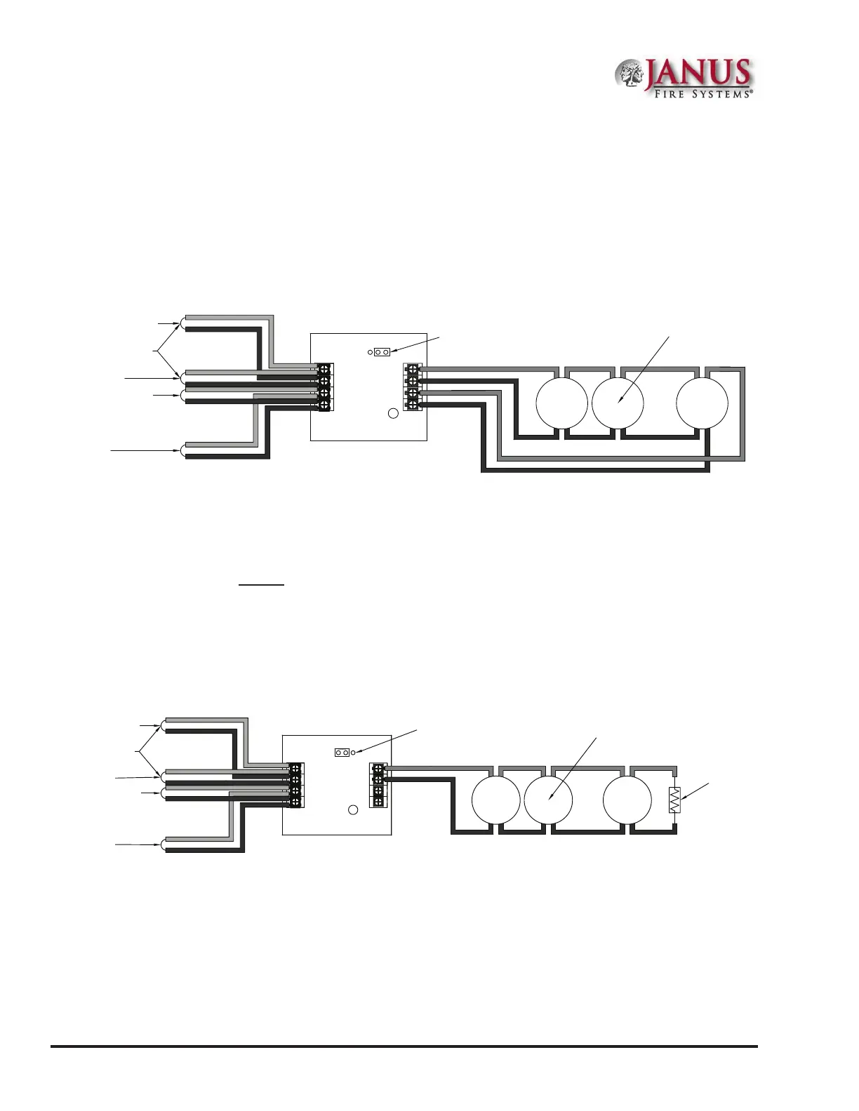
ConventionalInitiatingZones(CIZM-4)ClassA
Figure 11. CIZM-4, Class A
Note: The resistance of external wiring shall be less that 100Ω.
The capacitance of external wiring shall be less than 1 micro farads.
From FACP or
Previous Module
To Next Module
From FACP
or Previous Module
To Next
Module
24-
24+
S-
S+
SLC Loop
LED
JP1
Select Style D
Conventional
Detector
_
+
_
+
_
+
Conventional Initiating Zone Module
Model No. CIZM-4
A-
A+
B-
B+
DWG #593-11
Notes:
1. e resistance of external wiring shall be less than 100 ohms.
2. e capacitance of external wiring shall be less than 1 micro F.
3. In this style, the open circuit “trouble condition” of IDC is latched at the control panel until system is reset.
erefore, the system MUST be reset at the control panel after clearing the open circuit condition at the
site.
4. Refer to the CIZM data sheet for information on compatible devices.
ConventionalInitiatingZones(CIZM-4)ClassB
Figure 12. CIZM-4, Class B
Conventional Initiating Zone Module
Model No. CIZM-4
Note: The resistance of external wiring shall be less that 100Ω.
The capacitance of external wiring shall be less than 1 micro farads.
From FACP or
Previous Module
To Next Module
From FACP or
Previous Module
To Next Module
24-
24+
S-
S+
A-
A+
SLC Loop
LED
JP1
Conventional
Detector
5.1KΩ 1/2W
EOLR
_
+
_
+
_
+
B-
B+
Select Style B
DWG #593-12