Page: 33
JFS-A1 INSTALLATION, OPERATION, AND INSTRUCTION MANUAL
Document # : DOC230
Issued: August 27, 2012
Revised: N/A
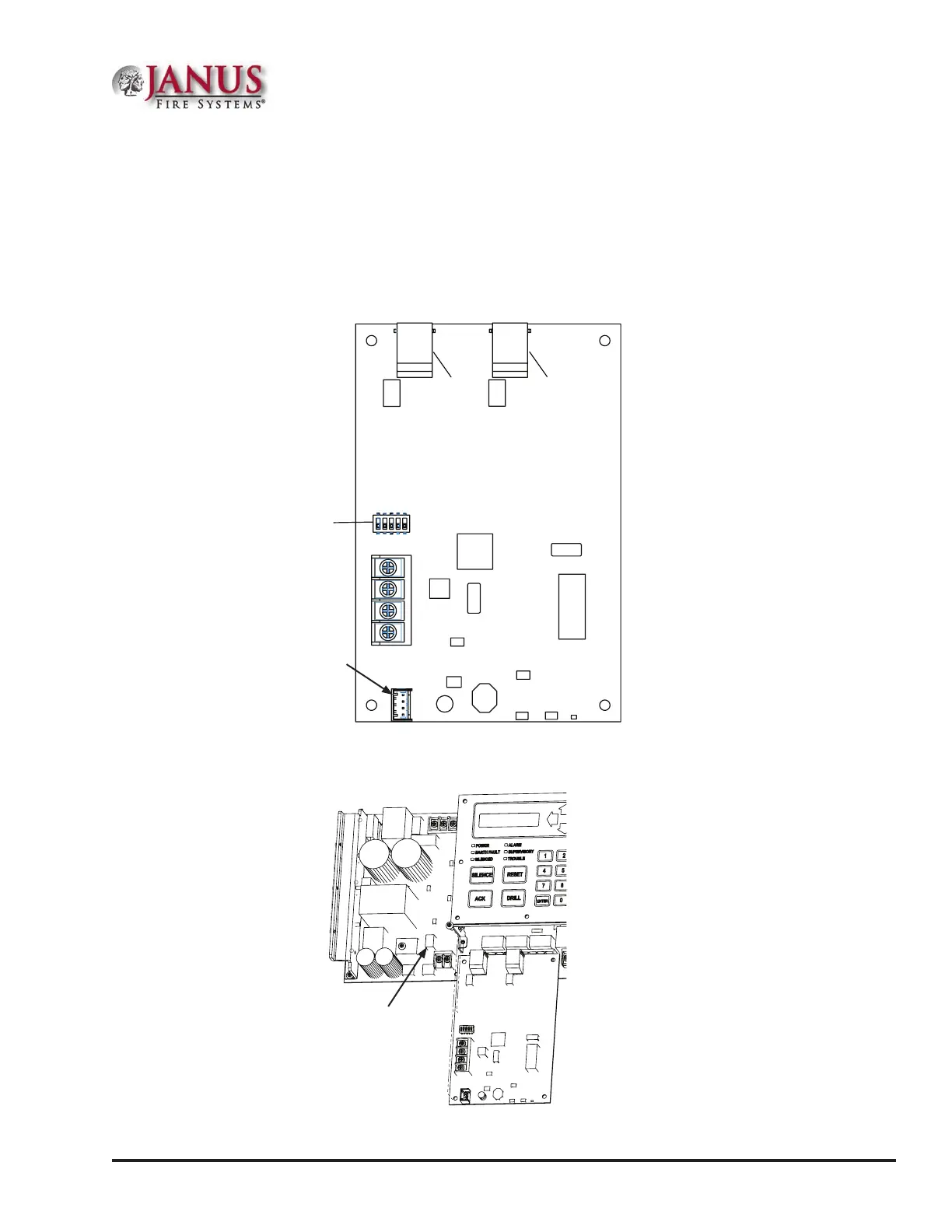
Dip Switch Location
e UD-1000 is connected to the P-Link bus and must be programmed with an address between one and thirty-
one (1–31) for proper operation. A four-wire cable (P/N 5210514) is supplied with the UD-1000, which should
be used to connect the P1 on the UD-1000 and the "P"connection on the main panel board. Please refer to the
following illustrations for the location of the P1 and main board connections.
Figure 35. UD-1000 Board Showing Location of Dip Switches & P1 Connector
Figure 36. JFS-A1 Main Board Showing Location of "P" Connection
DWG #593-33
Line #2
Line #1
Dip
Switches
P1 Connector
P Connector on
JFS-A1 main board
DWG #593-32B