Page: 17
JFS-A1 INSTALLATION, OPERATION, AND INSTRUCTION MANUAL
Document # : DOC230
Issued: August 27, 2012
Revised: N/A
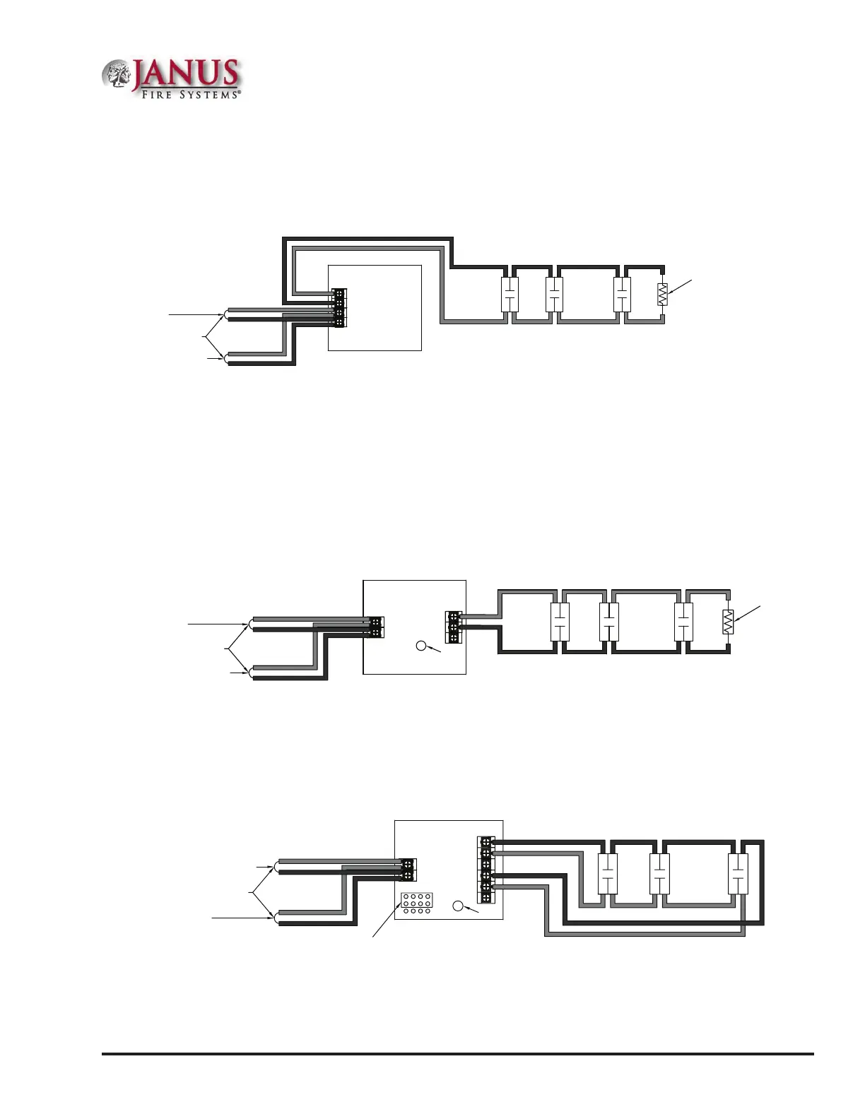
MiniatureContactModule(MCM)
Refer to the gure shown below for a MCM wiring example.
Figure 13. MCM Wiring Example
COM
NO
S-
S+
5.1KΩ 1/2W EOLR
SLC Loop
To Next Module
From FACP or Previous Module
Note: The resistance of external wiring shall be less that 100Ω.
The capacitance of external wiring shall be less than 1 micro farads.
Mini Contact Module
Model No. MCM
DWG #593-13
Note: If MCM is located in an electrical box, it should be secured using crew tabs or other method to prevent
movement.
SingleContactModule–4inchMount(SCM-4)
Refer to the gure shown below for a SCM-4 wiring example.
Figure 14. SCM-4 Wiring Example
COM
NO
S-
S+
SLC Loop
To Next Module
From FACP or Previous Module
Single Contact Module
Model No. SCM-4
5.1KΩ 1/2W EOLR
Note: The resistance of external wiring shall be less that 100Ω.
The capacitance of external wiring shall be less than 1 micro farads.
Z
LED
DWG #593-14
DualContactModule–4inchMount(DCM-4)
Refer to the gure shown below for a Class A DCM-4 wiring example.
Figure 15. DCM-4 with One Class A Circuit
S-
S+
SLC Loop
To Next Module
From FACP or Previous Module
Dual Contact Module
Model No. DCM-4
LED
Note: The resistance of external wiring shall be less that 100Ω.
The capacitance of external wiring shall be less than 1 micro farads.
JP1
Select Style 6
NO1
C1
Z1
NO2
C2
Z2
DWG #593-15
Note: In this conguration, the DCM-4 operates as a single point Class A module.