Page: 25
JFS-A1 INSTALLATION, OPERATION, AND INSTRUCTION MANUAL
Document # : DOC230
Issued: August 27, 2012
Revised: N/A
I/OCircuitConguration
e JFS-A1 is equipped with two (2) I/O circuits that may be congured as either input or output devices. e
panel has ground fault detection on the I/O circuits. e impedance to ground for ground fault detection is 0 ohms.
Note: e I/O circuits only operate as Class B. Refer to the gure shown below for a wiring example of an I/O
circuit conguration.
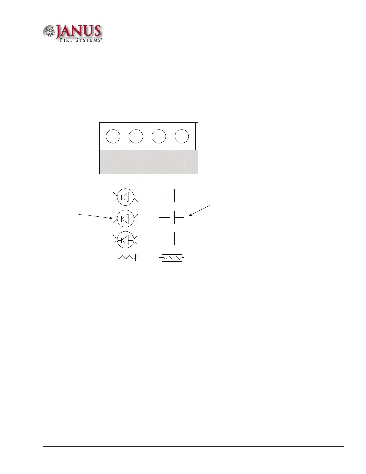
Figure 26. Example of I/O Circuit Wiring Example
I/O 1 I/O 2
- + - +
5.1k EOL
Potter Part #3005013
Notification
Appliance
5.1k EOL
Potter Part #3005013
Normally Open
Dry Contact
I/OCircuitsasInputs
When congured as inputs, the I/O circuits are used as a dry contact monitoring input.
Input Conguration Characteristics:
y Maximum allowable wire length is 10,000 feet.
y e selection of the contact input functions are the same as the MCM and SCM-4 modules.
I/OCircuitsasOutputs
When congured as outputs, each I/O circuit is rated for one (1) amp continuous current at 2.4 VDC.
Output Conguration Characteristics:
y Supervised and regulated by the main panel board.
y Reverse polarity upon activation.
y Circuits are power limited
y Type of output is selectable. Strobes can be synchronized with all compatible strobe devices, including Potter/
AMSECO®, Cooper Wheelock®, Gentex®, or System Sensor®.
I/OMaximumImpedanceFormula
e maximum impedance is a function of the load placed on the circuit. To calculate the maximum impedance, use
the following formula:
(Alarm Current of Notication Appliances) x (Wire Resistance) < 3 Volts
DWG #602-7A