Page: 12
JFS-A1 INSTALLATION, OPERATION, AND INSTRUCTION MANUAL
Document #: DOC230
Issued: August 27, 2012
Revised: N/A
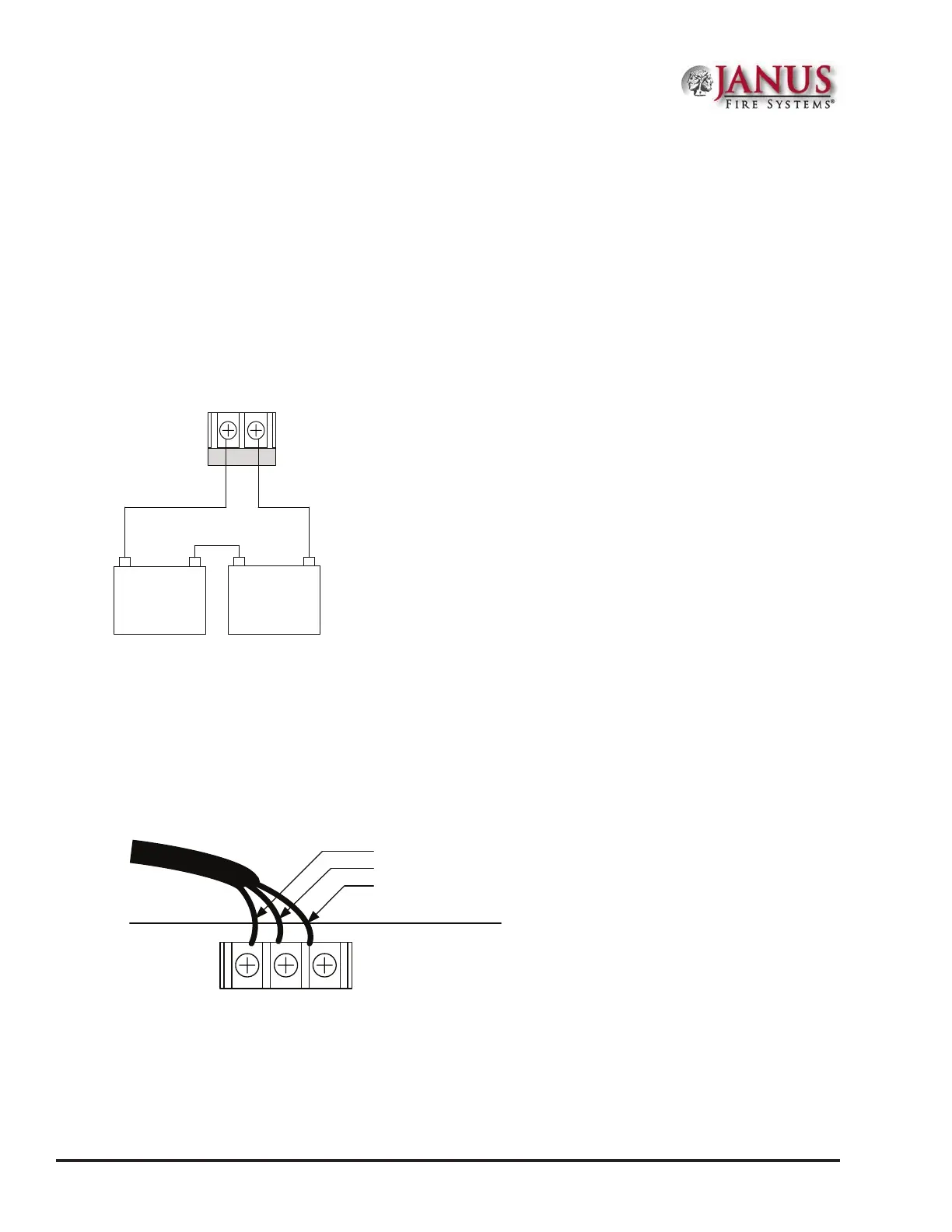
Battery Connections
e battery charging circuit is located on the main panel in the lower left portion of the board. e maximum
battery charging circuit is 1.0 amp DC; the charging voltage is approximately 27.3 VDC and is supervised.
Note: e battery should be clearly labeled as “Sealed Lead Acid Battery” or equivalent UL listed or UL
Recognized.
Connect the battery wire leads to the terminal connections, as shown. Batteries should be replaced every ve (5)
years or sooner depending on annual testing.
Figure 5. JFS-A1 Battery Connections
Panel
Connections
BATTERY
-+
12 V
Battery
-+
12 V
Battery
-+
DWG # 593-5
Main Supply Circuit
e AC terminals are located in the upper left hand portion of the main board. e main board supervises the main
AC power and provides indication that the AC power is absent.
Figure 6. JFS-A1 AC Terminals
BWG
AC120 V/AC230V,50/60H z
AC POWER
Black
White
Ground
240VAC 50/60 Hz
Connect to separate
Unswitched AC circuit
e terminals are rated at 120 VAC/240 VAC 50/60 Hertz and are marked accordingly on the board. e earth
ground connection is marked as “G” and is the furthest connection from the line voltage connection.
e AC input power ratings are as follows:
•y Maximum of 3A at the nominal 120 VAC rating.
•y Maximum of 2A at the nominal 240 VAC rating.