130
Appendix A—Description of parameters
VARIABLE SPEED DRIVE SERIES III LIT-12012999—June 2018 www.johnsoncontrols.com
Appendix A—Description of parameters
On the following pages you will find the parameter descriptions arranged according to the parameter number.
Some parameter names are followed by a number code indicating the applications in which the parameter is included. See the
list of applications below. The parameter numbers under which the parameter appears in different applications are also given.
Application level
1 Basic
2 PID
3 Advanced
Code Modbus ID Parameter Application RO/RW
P1.1 101 Min Frequency 1,2,3 RW
Sets the lower limit for the frequency of the motor. This will limit other frequency parameter settings;
Preset Speeds, Jog Speed, 4mA Fault preset speed, Fire Mode speed, and brake speed settings.
P1.2 102 Max Frequency 1,2,3 RW
Sets the upper limit for the frequency of the motor. This will limit other frequency parameter settings;
Preset Speeds, Jog Speed, 4mA Fault preset speed, Fire Mode speed, and brake speed settings.
P1.3 103 Accel Time 1 1,2,3 RW
Use this parameter to set the acceleration ramp time 1 in seconds.
P1.4 104 Decel Time 1 1,2,3 RW
Use this parameter to set the deceleration ramp time 1 in seconds.
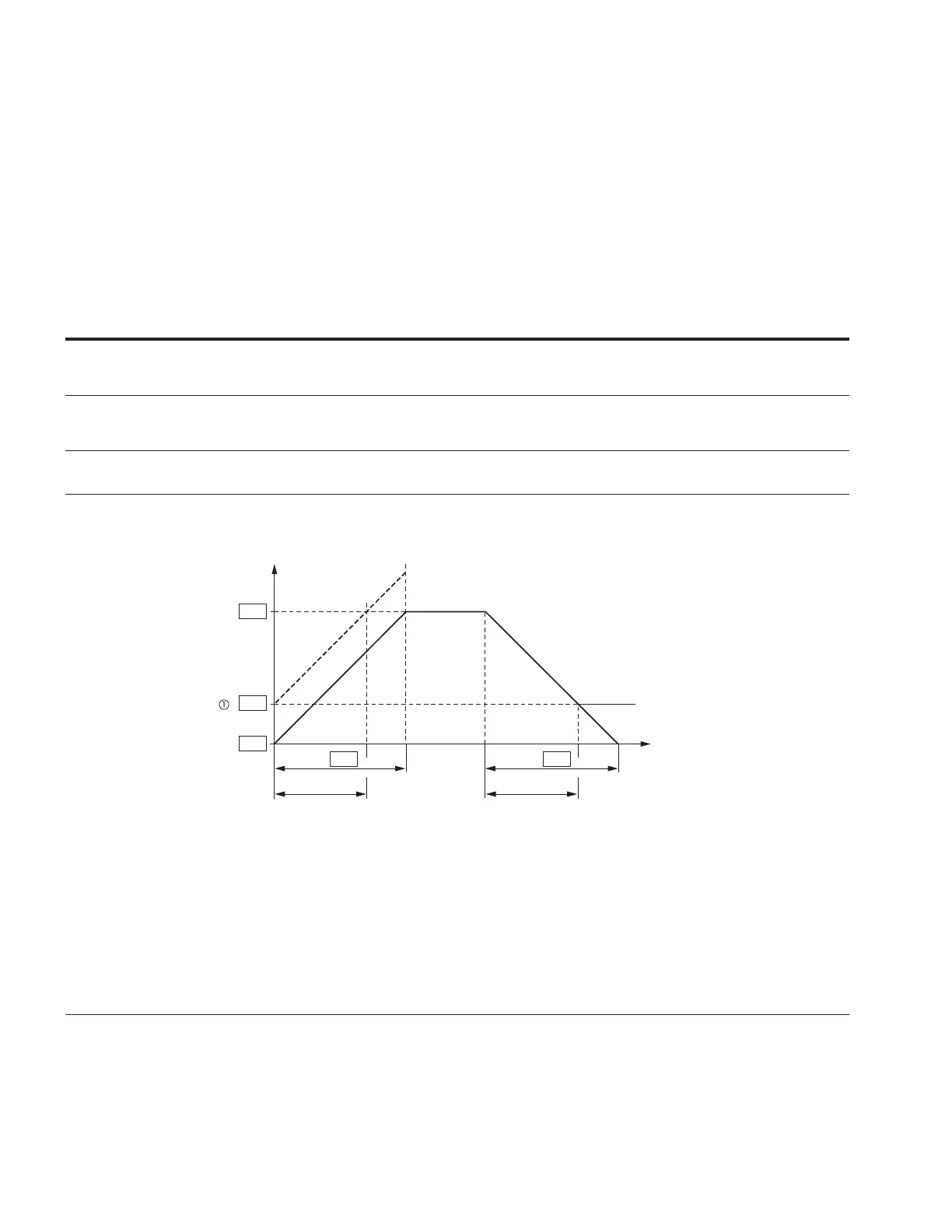
Figure 28. Acceleration and deceleration time
(Hz)
t (s)
f
out
P1.1
P1.2
P1.1
P1.3 P1.4
t
1
t
2
The values for the acceleration time t
1
and the deceleration time t
2
are calculated as follows:
t
1
=
(P1.2–P1.1) x P1.3
P1.2
t
2
=
(P1.2–P1.1) x P1.4
P1.2
The defined acceleration (ID103) and deceleration times ID104 apply for all changes to the frequency
setpoint value.
If the start-release (FWD, REV) is switched off, the output frequency (f
Out
) is immediately set to zero. The
motor runs down uncontrolled.
If a controlled run-down is requested (with value from ID104), stop mode should be set to ramp.
When setting a minimum output frequency (ID104 greater than 0 Hz), the acceleration and deceleration
time of the drive is reduced to t
1
or t
2
.