148
Appendix A—Description of parameters
VARIABLE SPEED DRIVE SERIES III LIT-12012999—June 2018 www.johnsoncontrols.com
Code Modbus ID Parameter Application RO/RW
P2.4.5 174 AI1 Filter Time 1,2,3 RW
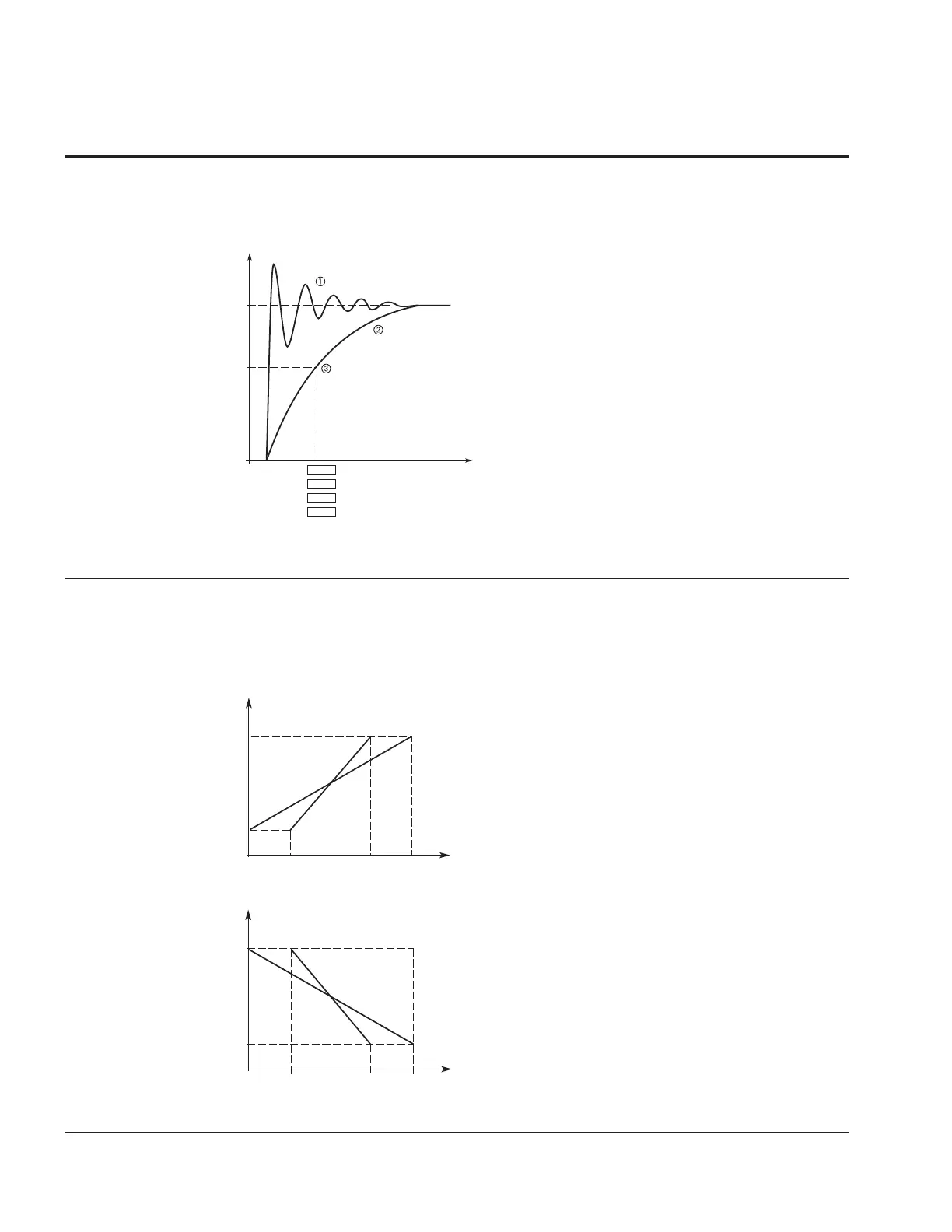
When this parameter is given a value greater than 0, the function that filters out disturbances from the
incoming analog signal is activated.
A long filtering time makes the regulation response slower.
Figure 42. AI1 signal filtering
AI
AO
100%
63%
t (s)
P2.5
P2.15
P4.4
P4.11
AI1
AI2
AO1
AO2
otes: N
Analog signal with faults (unfiltered).
Filtered analog signal.
Filter time constant at 63% of the set value.
P2.4.6 181 AI1 Signal Invert 1,2,3 RW
This parameter is used to invert the logic of the analog input.
0 No Inversion = no inversion of analog Vin signal takes place. 0V/0(4)mA = min frequency, 10V/20mA =
max frequency
1 Inverted = inversion of analog signal takes place. 0V/0(4)mA = max frequency, 10V/20mA = min
frequency.
Figure 43. AI1 No signal inversion
Output
Frequency
P2.22
P2.21
0
100%
AI1
(Term. 2)
P2.4/2.14P2.3/2.13
P2.2/2.12 = 0
AI1 = 0 – 100%
P2.2/2.12 = 1
AI1 = Custom
Figure 44. AI1 Signal Inversion
Output
Frequency
P2.22
P2.21
0
100%
AI1
(Term. 2)
P2.4/2.14
P2.3/2.13
P2.2/2.12 = 0
AI1 = 0 – 100%
P2.2/2.12 = 1
AI1 = Custom
Maximum AI1 signal = minimum set speed.
Minimum AI1 signal = maximum set speed.