146
Appendix A—Description of parameters
VARIABLE SPEED DRIVE SERIES III LIT-12012999—June 2018 www.johnsoncontrols.com
Code Modbus ID Parameter Application RO/RW
P2.2.47 226 Start Timer 3 2,3 RW
Use this parameter for selecting an external input for enabling the timer functions to begin
counting. When this function is set for Normally Open the drive will not start the Timer sequence. If
the function is set for Normally Close the Timer function will start. When assigned to an input the input
active will start the timer. Can be set to DigiIN:X indicates on board terminal inputs, DigiIN:A:IOX:X
indicates optional board inputs in A slot, DigiIN:B:IOX:X indicates optional board inputs in B slot, or
Timer Channel X. RO X Function allows for having an input turn on without having to hard wire it to the
physical relay output.
Closed contact: Timer1,Timer2 or Timer3 will be started.
P2.3.1 105 Preset Speed 1 1,2,3 RW
Use this parameter to set the Preset Frequency 1.
P2.3.2 106 Preset Speed 2 1,2,3 RW
Use this parameter to set the Preset Frequency 2.
P2.3.3 118 Preset Speed 3 1,2,3 RW
Use this parameter to set the Preset Frequency 3.
P2.3.4 119 Preset Speed 4 1,2,3 RW
Use this parameter to set the Preset Frequency 4.
P2.3.5 120 Preset Speed 5 1,2,3 RW
Use this parameter to set the Preset Frequency 5.
P2.3.6 121 Preset Speed 6 1,2,3 RW
Use this parameter to set the Preset Frequency 6.
P2.3.7 122 Preset Speed 7 1,2,3 RW
Use this parameter to set the Preset Frequency 7.
P2.3.8 117 Jog Reference 1,2,3 RW
Use this parameter to set the jogging speed set point, this speed is selected with the digital input
programmed for Jogging speed. When enabled the drive starts and ramps to this speed, input removed
drive stops.
This parameter’s value is automatically limited between minimum and maximum frequency.
P2.4.1 222 AI1 Mode 1,2,3 RW
Defines the analog input 1 source mode for current or voltage, also need to set DIP switches on control
board SW1.
0 = 0-20mA - current loop with an external supply the ground jumper is not required.
1 = 0-10V - If using the 10V supply on Terminal 1 of the drive, it will require a ground jumper from
Terminal 6 to the AI- input terminal 3.
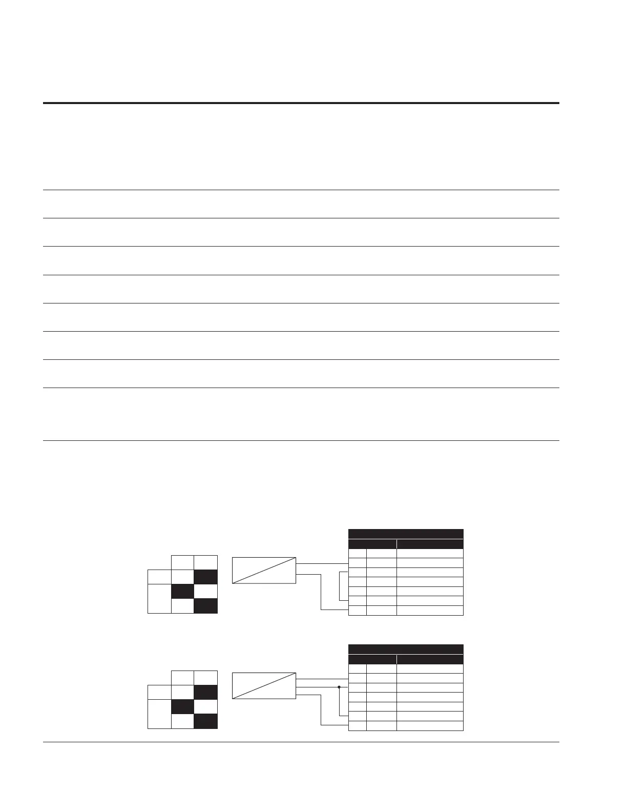
Figure 37. AI1 2wire-current
OFF
2-wire Transmitter
1 10V+ 10V supply
2 AI1+ Analog input 1+
3 AI1- Analog input 1-
4 AI2+ Analog input 2+
5 AI2- Analog input 2-
6 GND I/O Ground
13 24Vo 24V auxillary voltage
Actual
Value
I = (0)4...20mA
−
+
ON
AI
AI2
Standard I/O Board
Terminal
Signal
Figure 38. AI1 3wire-current
OFF
3-wire transducer
1 10V+ 10V supply
2 AI1+ Analog input 1+
3 AI1- Analog input 1-
4 AI2+ Analog input 2+
5 AI2- Analog input 2-
6 GND I/O Ground
13 24Vo 24V auxillary voltage
Actual
Value
I = (0)4...20mA
POW
−
+
ON
AI
AI2
Standard I/O Board
Terminal
Signal