134
Appendix A—Description of parameters
VARIABLE SPEED DRIVE SERIES III LIT-12012999—June 2018 www.johnsoncontrols.com
Code Modbus ID Parameter Application RO/RW
P2.1.5 145 AI Ref Scale Max Value 1,2,3 RW
Max Frequency when max of Analog Reference is applied. With values set at 0 scaling will follow the
maximum frequency value parameter Para ID 102.
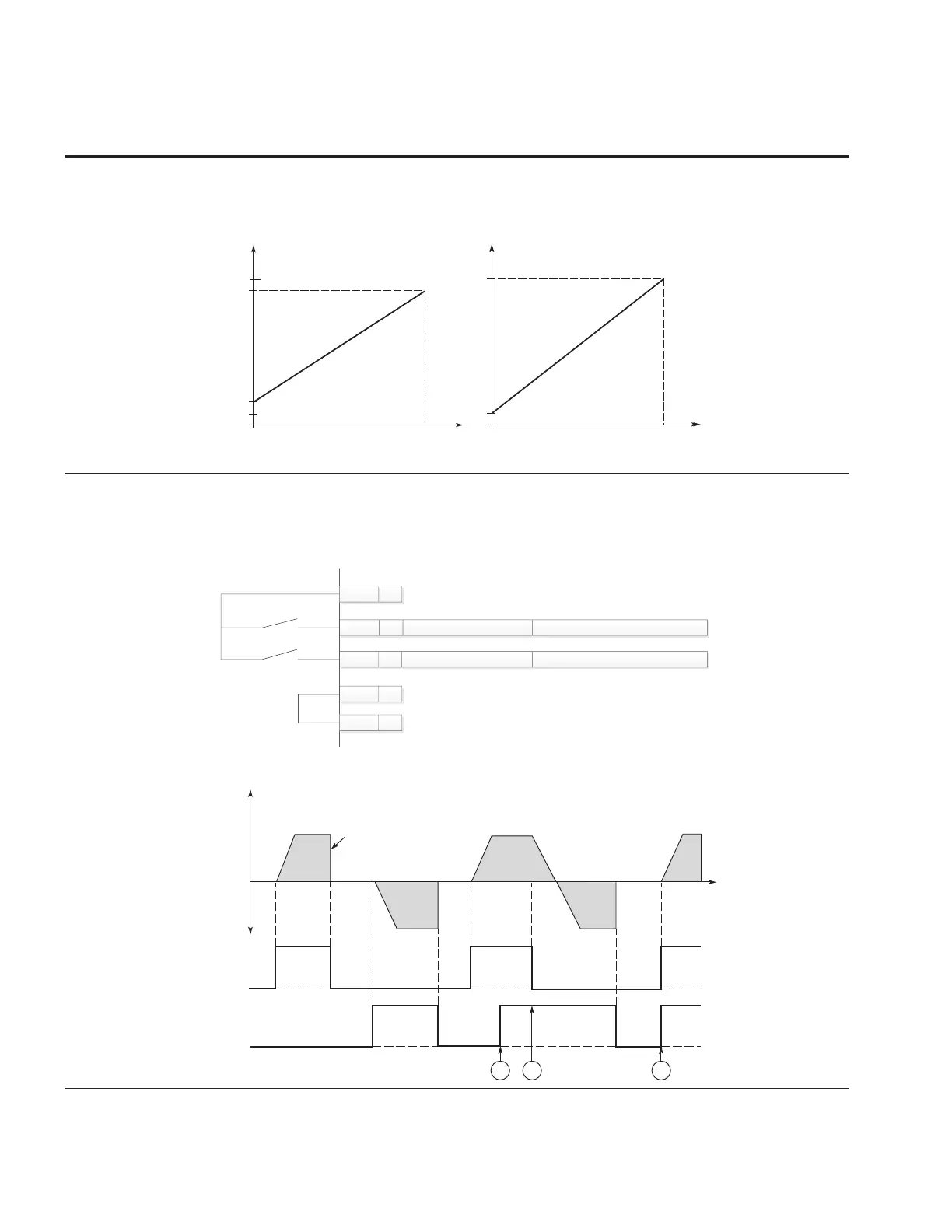
Figure 30. With and without reference scaling
Output
Frequency
Max. Frequency P1.2
Min. Frequency P1.1
010
Analog
Input [V]
Output
Frequency
Max. Frequency P1.2
Min. Frequency P1.1
010
Analog
Input [V]
Ref. Scaling Max. Value (P2.22)P2.22
P2.21
With Reference Scaling
(Reference Scaling)
With Reference Scaling
(No scaling used [P2.21 = 0])
P2.2.1 143 IO Terminal 1 Start Stop Logic 1,2,3 RW
This parameter defines the start and stop of the drive with the digital signals.
0 = Para ID 190: DI closed contact = start forward Para ID 191: DI closed contact = start reverse - This
would be considered 2 wire control with either a contact used on the Start FWD or Start REV
commands. Contacts Open the motor stops.
24V+
DIN1 20
DIN2 21
CMA 24
GND 12
ID190 - Start Signal: DigIN:1 ID143 Start Stop Logic: Start Forward
ID191- Start Signal 2: DigIN:2 ID143 Start Stop Logic: Start Reverse
15
Figure 31. Start forward/start reverse
1
FWD
REV
DIN1
DIN2
t
Output
Frequency
Stop Function
(P7.10) = Coasting
2 3