150
Appendix A—Description of parameters
VARIABLE SPEED DRIVE SERIES III LIT-12012999—June 2018 www.johnsoncontrols.com
Code Modbus ID Parameter Application RO/RW
P2.4.10 133 AI1 Joystick Offset 3 RW
This parameter defines the mid point of the analog joystick control. By moving the offset in a positive
or negative direction will cause the min frequency crossing point to be move between +/-50% of the
analog input scale.
P2.5.1 223 AI2 Mode 1,2,3 RW
Defines the analog input 2 source mode for current or voltage, also need to set DIP switches on control
board SW2 and 3.
0 = 0-20mA - current loop with an external supply the ground jumper is not required.
1 = 0-10V - If using the 10V supply on Terminal 1 of the drive, it will require a ground jumper from
Terminal 6 to the AI- input terminal 3.
2 = -10V to +10Vdc - Voltage loop with a +10 and a -10 volt differential supply.
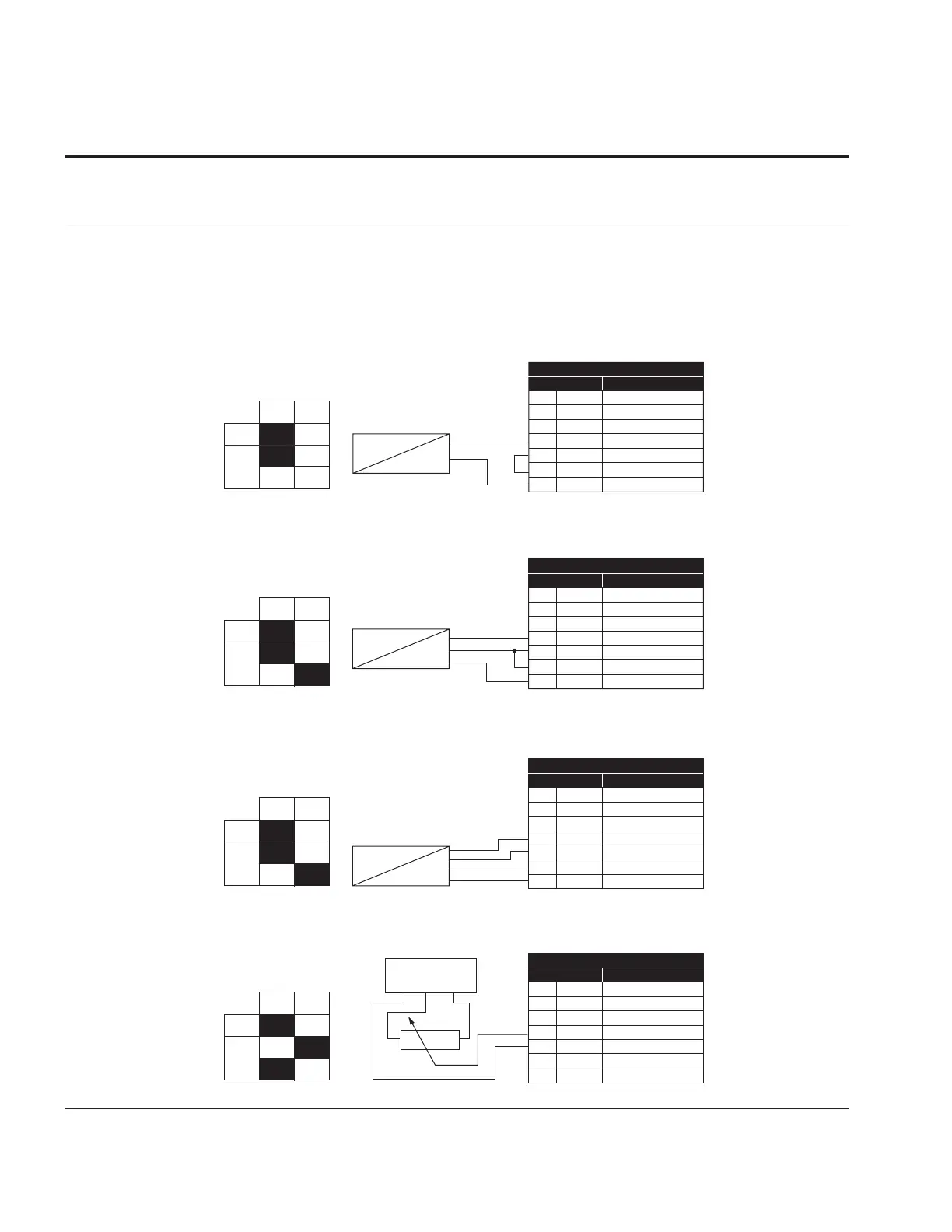
Figure 47. AI2 2wire-current
OFF
2-wire Transmitter
1 10V+ 10V supply
2 AI1+ Analog input 1+
3 AI1- Analog input 1-
4 AI2+ Analog input 2+
5 AI2- Analog input 2-
6 GND I/O Ground
13 24Vo 24V auxillary voltage
Actual
Value
I = (0)4...20mA
−
+
ON
AI
AI2
Standard I/O Board
Terminal
Signal
Figure 48. AI2 3wire-current
3-wire transducer
1 10V+ 10V supply
2 AI1+ Analog input 1+
3 AI1- Analog input 1-
4 AI2+ Analog input 2+
5 AI2- Analog input 2-
6 GND I/O Ground
13 24Vo 24V auxillary voltage
Actual
Value
I = (0)4...20mA
POW
−
+
Standard I/O Board
Terminal
Signal
OFF
ON
AI
AI2
Figure 49. AI2 4wire-current
1 10V+ 10V supply
2 AI1+ Analog input 1+
3 AI1- Analog input 1-
4 AI2+ Analog input 2+
5 AI2- Analog input 2-
6 GND I/O Ground
13 24Vo 24V auxillary voltage
4-wire transducer
Actual
Value
I = (0)4...20mA
POW
GND
−
+
Standard I/O Board
Terminal
Signal
OFF
ON
AI
AI2
Figure 50. AI2 differential voltage
1 10V+ 10V supply
2 AI1+ Analog input 1+
3 AI1- Analog input 1-
4 AI2+ Analog input 2+
5 AI2- Analog input 2-
6 GND I/O Ground
13 24Vo 24V auxillary voltage
OFF
ON
AI
AI2
Standard I/O Board
Terminal
Signal
Ext. 10V supply
GND -10V +10V