137
Appendix A—Description of parameters
VARIABLE SPEED DRIVE SERIES III LIT-12012999—June 2018 www.johnsoncontrols.com
Code Modbus ID Parameter Application RO/RW
P2.2.4 2206 IO Terminal 2 Start Stop Logic 1,2,3 RW
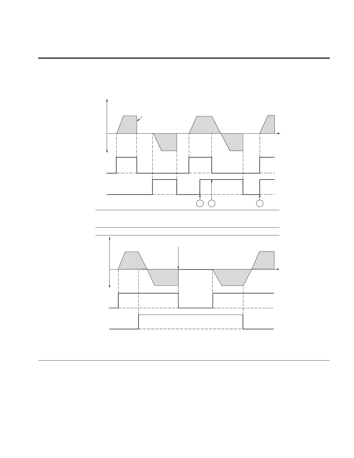
This parameter defines the start and stop of the drive with the digital signals.
0 = Para ID 2207: DI closed contact = start forward Para ID 2208: DI closed contact = start reverse -
This would be considered 2 wire control with either a contact used on the Start FWD or Start REV
commands. Contacts Open the motor stops.
Figure 34. Start forward/start reverse
1
FWD
REV
DIN1
DIN2
t
Output
Frequency
Stop Function
(P7.10) = Coasting
2 3
1 = Para ID 2207: DI closed contact = start /open contact = stop Para ID 2208: DI closed contact =
reverse / open contact = forward - This would be considered 2 wire control with a contact on start/
stop, contact open it stops and direction on 2nd start signal.
Figure 53. Start, stop and reverse
FWD
REV
DIN1
DIN2
Output
Frequency
Stop Function
(P7.10) = Coasting
t
Notes:
The first selected direction has the highest priority.
When the DIN1 contact opens the direction of rotation starts to change.
If Start forward (DIN1) and Start reverse (DIN2) signals are active simultaneously the Start
forward signal (DIN1) has priority.