138
Appendix A—Description of parameters
VARIABLE SPEED DRIVE SERIES III LIT-12012999—June 2018 www.johnsoncontrols.com
Code Modbus ID Parameter Application RO/RW
P2.2.4 2206 2 = Para ID 2207: DI closed contact = start / open contact = stop Para ID 2208: DI closed contact = start
enabled / open contact = start disabled and drive stopped if running Motor direction keeps forward
- This would be considered 3 wire control with Start signal 2 required to be closed to enable Start on
Start signal 1.
1,2,3 RW
3 = Three-wire connection (pulse control): Para ID 2207: DI changes from open to closed = start pulse
Para ID 2208: DI changes from closed to open = stop pulse Para ID 198: DI closed contact = reverse/
open contact = forward - This would be considered 3 wire control with Start Signal 1 being the Start
Pulse and Start Signal 2 being the NC Stop.
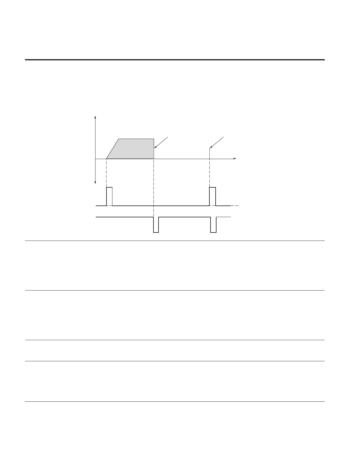
Figure 35. Start pulse/stop pulse
t
Output
Frequency
Stop Function
(P7.10) = Coasting
If Start and Stop pulses are
simultaneous the Stop pulse
overrides the Start pulse
REV
DIN1
Start
DIN2
Stop
P2.2.5 2207 IO Terminal 2 Start Signal 1 1,2,3 RW
The 2
nd
Signal selection 1 for the start/stop logic listed in parameter Para ID 2206. When the parameter
is set to DigIN: 1 it references DIN1 on the control board, selecting different DIGIN values will assign it
to a different input on the control board or option card. When set to Normally Open this function would
be always tied low or 0 when using I/O terminal 1 as the control place. When value is set to Normally
Closed this will cause the function to be always on and activate the output if I/O Terminal 1 is the
current control place. Can be set to DigiIN:X indicates on board terminal inputs, DigiIN:A:IOX:X indicates
optional board inputs in A slot, DigiIN:B:IOX:X indicates optional board inputs in B slot, or Timer
Channel X
P2.2.6 2208 IO Terminal 2 Start Signal 2 1,2,3 RW
The 2
nd
Signal selection 2 for the start/stop logic listed in parameter Para ID 2206. When the parameter
is set to DigIN: 2 it references DIN2 on the control board, selecting different DIGIN values will assign it
to a different input on the control board or option card. When set to Normally Open this function would
be always tied low or 0 when using I/O terminal 1 as the control place. When value is set to Normally
Closed this will cause the function to be always on and activate the output if I/O Terminal 1 is the
current control place. Can be set to DigiIN:X indicates on board terminal inputs, DigiIN:A:IOX:X indicates
optional board inputs in A slot, DigiIN:B:IOX:X indicates optional board inputs in B slot, or Timer
Channel X
P2.2.7 881 Thermistor Input Select 1,2,3 RW
This parameter defines DIN7, and DIN8 is digital input or thermistor input. When this parameter is
enabled it switches DIN7 and DIN8 to a thermistor input that triggers at 4.7k ohm.
P2.2.8 198 Reverse 1,2,3 RW
Use this parameter for switching the direction of the motor to reverse when using 3 wire start/stop logic
parameter in Para ID 143 = 3. Can be set to DigiIN:X indicates on board terminal inputs, DigiIN:A:IOX:X
indicates optional board inputs in A slot, DigiIN:B:IOX:X indicates optional board inputs in B slot, or
Timer Channel X
Contact Open = Forward direction.
Contact Close = Reverse direction.