174
Appendix A—Description of parameters
VARIABLE SPEED DRIVE SERIES III LIT-12012999—June 2018 www.johnsoncontrols.com
Code Modbus ID Parameter Application RO/RW
P6.1.8 314 Stall Current Limit 1,2,3 RW
This parameter is used to set the current level when above the unit will stall. For a stall stage to
occur, the current must have exceeded this limit. The software does not allow entering a greater value
than In-Motor*2. If nominal motor current is changed, this parameter is automatically restored to the
default value (IL).
Figure 64. Stall characteristics settings
Stall Area
P9.12
P9.14
f
I
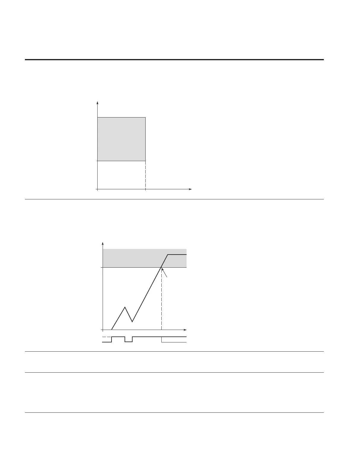
P6.1.9 315 Stall Time Limit 1,2,3 RW
This parameter is used to set the time limit before a stall error occurs.
The stall time is counted by an internal up/down counter based off the current being above the
limit setting. If the stall time counter value goes above this limit the protection will cause a trip
(see Para ID313).
Figure 65. Stall time count
Stall Time Counter
Trip Area
P9.13
Stall
No Stall
Time
Trip/ Warning
P9.11
P6.1.10 316 Stall Frequency Limit 1,2,3 RW
This parameter is used to set the freqeuncy level where below it a stall condition and is above the
current limit for the stall time to occur.
P6.1.11 317 Underload Protection 1,2,3 RW
This parameter is used to set the device reaction to an “UnderLoad Motor” condition. Deactivating the
protection by setting the parameter to 0 will reset the underload time counter to zero.
0 = No response
1 = Warning
2 = Fault, stop mode after fault according to standard stop mode
3 = Fault, stop mode after fault always by coasting