136
Appendix A—Description of parameters
VARIABLE SPEED DRIVE SERIES III LIT-12012999—June 2018 www.johnsoncontrols.com
Code Modbus ID Parameter Application RO/RW
P2.2.1 143 3 = Three-wire connection (pulse control): Para ID 190: DI changes from open to closed = start pulse Para
ID 191: DI changes from closed to open = stop pulse Para ID 198: DI closed contact = reverse/ open
contact = forward - This would be considered 3 wire control with Start Signal 1 being the Start Pulse
and Start Signal 2 being the NC Stop.
1,2,3 RW
24V+
DIN1 20
DIN2 21
CMA 24
GND 12
ID190 - Start Signal1: DigIN:1 ID143 Start Stop Logic: Start P
ID191- Start Signal 2: DigIN:2 ID143 Start Stop Logic: Stop P
15
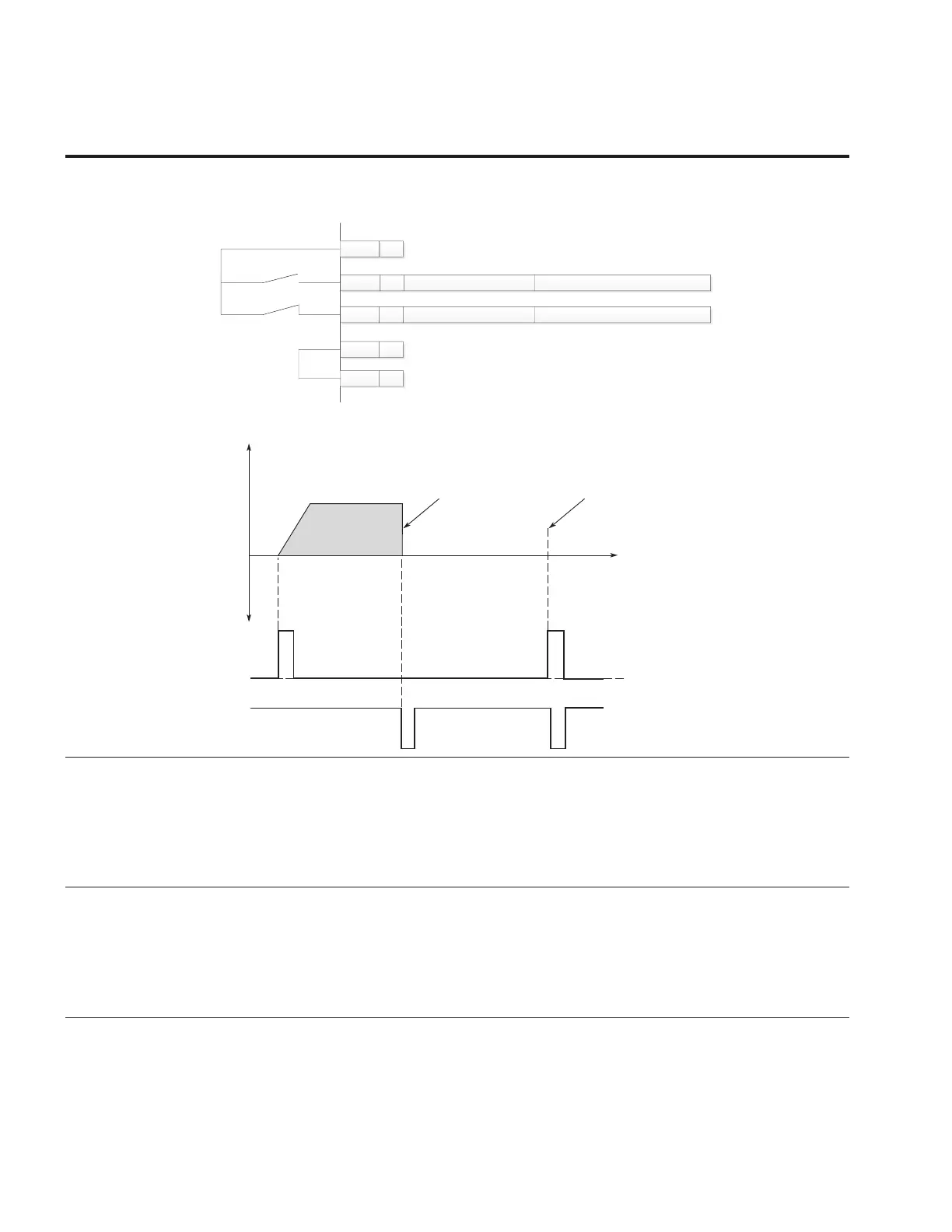
Figure 33. Start pulse/stop pulse
t
Output
Frequency
Stop Function
(P7.10) = Coasting
If Start and Stop pulses are
simultaneous the Stop pulse
overrides the Start pulse
REV
DIN1
Start
DIN2
Stop
P2.2.2 190 IO Terminal 1 Start Signal 1 1,2,3 RW
Signal selection 1 for the start/stop logic listed in parameter Para ID 143. This parameter would
correspond to the function listed for DIN1. When the parameter is set to DigIN: 1 it references DIN1 on
the control board, selecting different DIGIN values will assign it to a different input on the control board
or option card. When set to Normally Open this function would be always tied low or 0 when using
I/O terminal 1 as the control place. When value is set to Normally Closed this will cause the function
to be always on and activate the output if I/O Terminal 1 is the current control place. Can be set to
DigiIN:X indicates on board terminal inputs, DigiIN:A:IOX:X indicates optional board inputs in A slot,
DigiIN:B:IOX:X indicates optional board inputs in B slot, or Timer Channel X
P2.2.3 191 IO Terminal 1 Start Signal 2 1,2,3 RW
Signal selection 2 for the start/stop logic listed in parameter Para ID 143. This parameter would
correspond to the function listed for DIN2. When the parameter is set to DigIN: 2 it references DIN2 on
the control board, selecting different DIGIN values will assign it to a different input on the control board
or option card. When set to Normally Open this function would be always tied low or 0 when using
I/O terminal 1 as the control place. When value is set to Normally Closed this will cause the function
to be always on and activate the output if I/O Terminal 1 is the current control place. Can be set to
DigiIN:X indicates on board terminal inputs, DigiIN:A:IOX:X indicates optional board inputs in A slot,
DigiIN:B:IOX:X indicates optional board inputs in B slot, or Timer Channel X