169
Appendix A—Description of parameters
VARIABLE SPEED DRIVE SERIES III LIT-12012999—June 2018 www.johnsoncontrols.com
Code Modbus ID Parameter Application RO/RW
P5.1.2 107 Current Limit 1,2,3 RW
This parameter determines the maximum motor current allowed from the frequency converter. When the
motor current hits this level it goes into the current controller and tries to limit the output frequency to
drop the current. This is not a fault trip limit.
P5.1.3 109 V/Hz Optimization 1,2,3 RW
Use this parameter to enable an increase in voltage to the motor change automatically, this allows the
motor to produce sufficient torque to start and run at low frequencies becuase of high starting torque
processes. The voltage increase depends on the motor type and power. When enabled this has an effect
on the linear V/hz curve. Best results can be obtained from doign a motor identification and run the
programmable V/hz curve.
Example:
What changes are required to start the load from 0 Hz?
First set the motor nominal values (Basic Parameter group).
Option 1: Activate the Automatic torque boost.
Option 2: Programmable V/Hz curve.
To obtain the required torque, the zero point voltage and midpoint voltage/frequency (in parameter
Motor Control group) need to be set, so that the motor can draw enough current at the low frequencies.
First set
parameter Para ID108 to Programmable V/Hz curve (value 2).
Increase the zero point voltage Para ID293 to get enough current at zero speed. Then set the midpoint
voltage
Para ID292 to 100% and the midpoint frequency Para ID291 to value Para ID292/100%*Para ID488.
Note: In high torque—low speed applications—it is likely that the motor will overheat. If the motor
has to run a prolonged time under these conditions, special attention must be paid to cooling the motor.
Use external cooling for the motor if the temperature tends to rise too high.
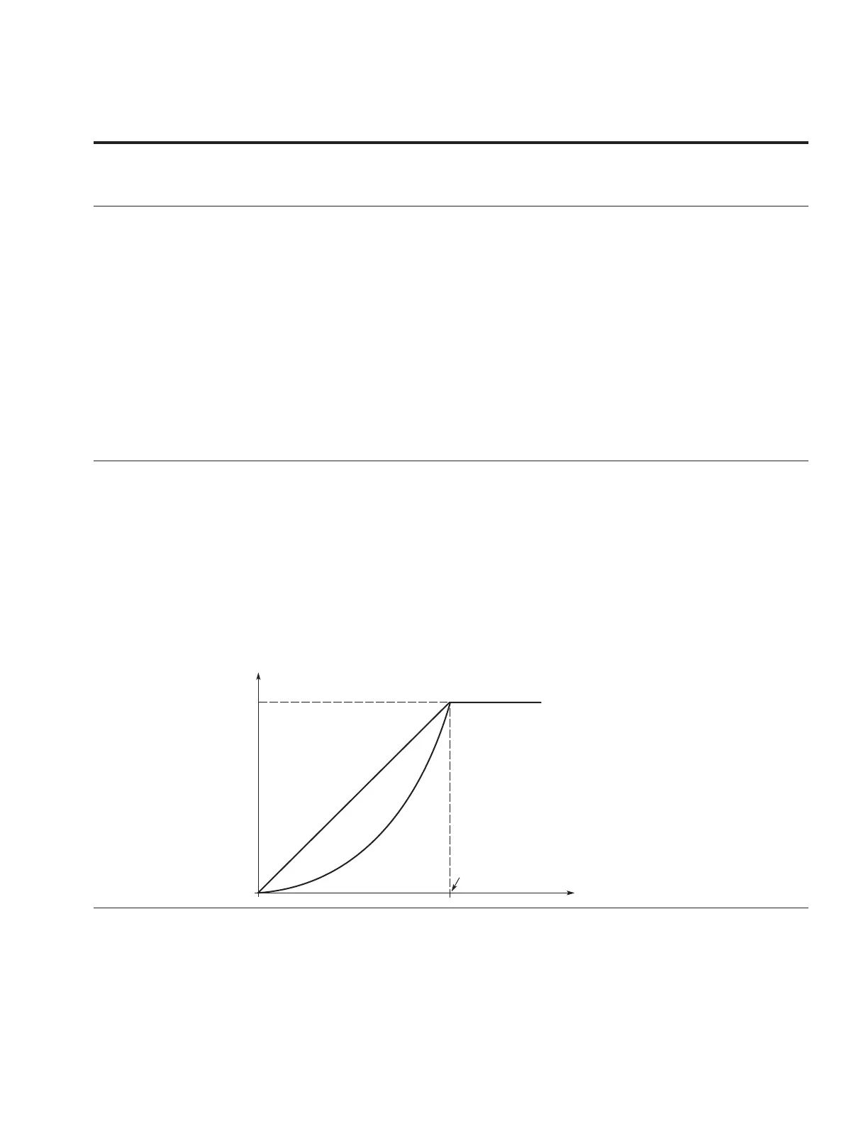
P5.1.4 108 V/Hz Ratio 1,2,3 RW
Use this parameter to set the type of V/Hz curve to use between the zero frequency and the field
weakening point.
Linear
0 = The voltage of the motor changes linearly with the frequency in the constant flux area from 0 Hz to
the field weakening point where the nominal voltage is supplied to the motor. A linear V/Hz ratio
should be used in constant torque applications. This default setting should be used if there is no
special need for another setting.
Squared
1 = The voltage of the motor changes following a squared curve form with the frequency in the area from
0 Hz to the field weakening point where the nominal voltage is supplied to the motor. The motor runs
under magnetized below the field weakening point and produces less torque and electromechanical
noise. A squared V/Hz ratio can be used in applications where the torque demand of the load is
proportional to the square of the speed, e.g., in centrifugal fans and pumps.
Programmable V/Hz curve
Figure 60. Linear and squared change of motor voltage
U[V]
f [Hz]
Linear
Squared
Un
P8.5
Default: Nominal
Voltage of the Motor
Field Weakening
Point
Default: Nominal
Frequency of the
Motor