151
Appendix A—Description of parameters
VARIABLE SPEED DRIVE SERIES III LIT-12012999—June 2018 www.johnsoncontrols.com
Code Modbus ID Parameter Application RO/RW
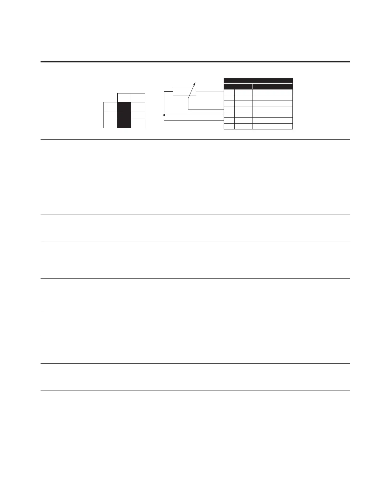
Figure 51. AI2 pot ref
1 10V+ 10V supply
2 AI1+ Analog input 1+
3 AI1- Analog input 1-
4 AI2+ Analog input 2+
5 AI2- Analog input 2-
6 GND I/O Ground
13 24Vo 24V auxillary voltage
OFF
ON
AI
AI2
Standard I/O Board
Terminal
Signal
P2.5.2 183 AI2 Signal Range 1,2,3 RW
Configures the Analog input 2 signal source scaling.
0 = 0-100%/0-20mA/0-10V - 0-100% is equal to 0 to 10V, 0-20mA
1= 20-100%/4-20mA/2-10V - 20-100% is equal to 2 to 10V, 4-20mA.
2 = “Customized,” see parameter Para ID 184 and 185, this defines the customized signal range.
P2.5.3 184 AI2 Custom Min 1,2,3 RW
Defines the custom min range of the analog input scale when the signal range is set for custom.
AI12Custom Min <= AI2 Custom Max.
P2.5.4 185 AI2 Custom Max 1,2,3 RW
Defines the custom max range of the analog input scale when the signal range is set for custom.
AI2 Custom Min <= AI2 Custom Max.
P2.5.5 182 AI2 Filter Time 1,2,3 RW
When this parameter is given a value greater than 0, the function that filters out disturbances from the
incoming analog signal is activated.
A long filtering time makes the regulation response slower.
P2.5.6 189 AI2 Signal Invert 1,2,3 RW
This parameter is used to invert the logic of the analog input.
0 No Inversion = no inversion of analog Vin signal takes place. 0V/0(4)mA = min frequency,
10V/20mA = max frequency
1 Inverted = inversion of analog signal takes place. 0V/0(4)mA = max frequency,
10V/20mA = min frequency.
P2.5.7 186 AI2 Joystick Hyst 3 RW
This parameter is used to set the analog joystick control hysteresis around the 0 speed reference.
To ignore values around the 0 speed reference, set the value greater then 0%, this will cause a +/- dead
band around the low analog reference. With an analog signal at 0+/- this value the reference will stay at
0Hz or min speed.
P2.5.8 187 AI2 Sleep Limit 3 RW
This parameter defines the sleep frequency level in the joystick control mode. The output of the drive
turns off if the joystick reference stays below the sleep limit for longer than the sleep delay time
parameter Para ID 188.
P2.5.9 188 AI2 Sleep Delay 3 RW
This parameter defines the joystick sleep delay time. If the joystick reference is below the sleep limit
level for the time defined the output of the drive will shutoff and be in sleep mode. Sleep function is
disabled when this value is set to 0.
P2.5.10 134 AI2 Joystick Offset 3 RW
This parameter defines the mid point of the analog joystick control. By moving the offset in a positive
or negative direction will cause the min frequency crossing point to be move between +/-50% of the
analog input scale.