161
Appendix A—Description of parameters
VARIABLE SPEED DRIVE SERIES III LIT-12012999—June 2018 www.johnsoncontrols.com
Code Modbus ID Parameter Application RO/RW
P3.2.36 1351 PID1 Superv Delay 2,3 RW
Use this parameter to set the delay time after which the PID feedback goes above or below the limit
settings to provide status to relay output function.
P3.2.37 1408 PID2 Superv Enable 2,3 RW
Use this parameter to select enabling of the upper and lower limits around the reference are set. When
the actual value goes above or below these, a counter starts counting up toward the Delay. When the
actual value is within the allowed area, the same counter counts down instead. After the delay time it
will turn on an relay output value.
P3.2.38 1409 PID2 Superv Upper Limit 2,3 RW
Use this parameter to set the upper PID feedback supervision limit level.
P3.2.39 1411 PID2 Superv Lower Limit 2,3 RW
Use this parameter to set the lower PID feedback supervision limit level.
P3.2.40 1413 PID2 Superv Delay 2,3 RW
Use this parameter to set the delay time after which the PID feedback goes above or below the limit
settings to provide status to relay output function.
P3.3.1 227 AO1 Mode 1,2,3 RW
Use this parameter to select the analog output mode for AO1 to be current or voltage. There are internal
relays to perform the switching of the signal between mA or V.
P3.3.2 146 AO1 Function 1,2,3 RW
Use this parameter to select the function or signal that is connected to the terminal AO1 terminal 22.
Scaling will very based on the signal selected.
P3.3.3 149 AO1 Minimum 1,2,3 RW
Use this parameter to define the signal minimum range setting to be either 0 mA or 4 mA (AO1 mode =
0–20 mA); 0V or 2V (AO1 mode = 0–10V).
0 = Set minimum value to 0V/0 mA.
1 = Set minimum value to 2V/4 mA.
P3.3.4 147 AO1 Filter Time 1,2,3 RW
Use this parameter to define the filtering time for the analog output signal, with a higher number
the more filtering time is added on the output signal. Setting this parameter value to 0.00 will
deactivate filtering.
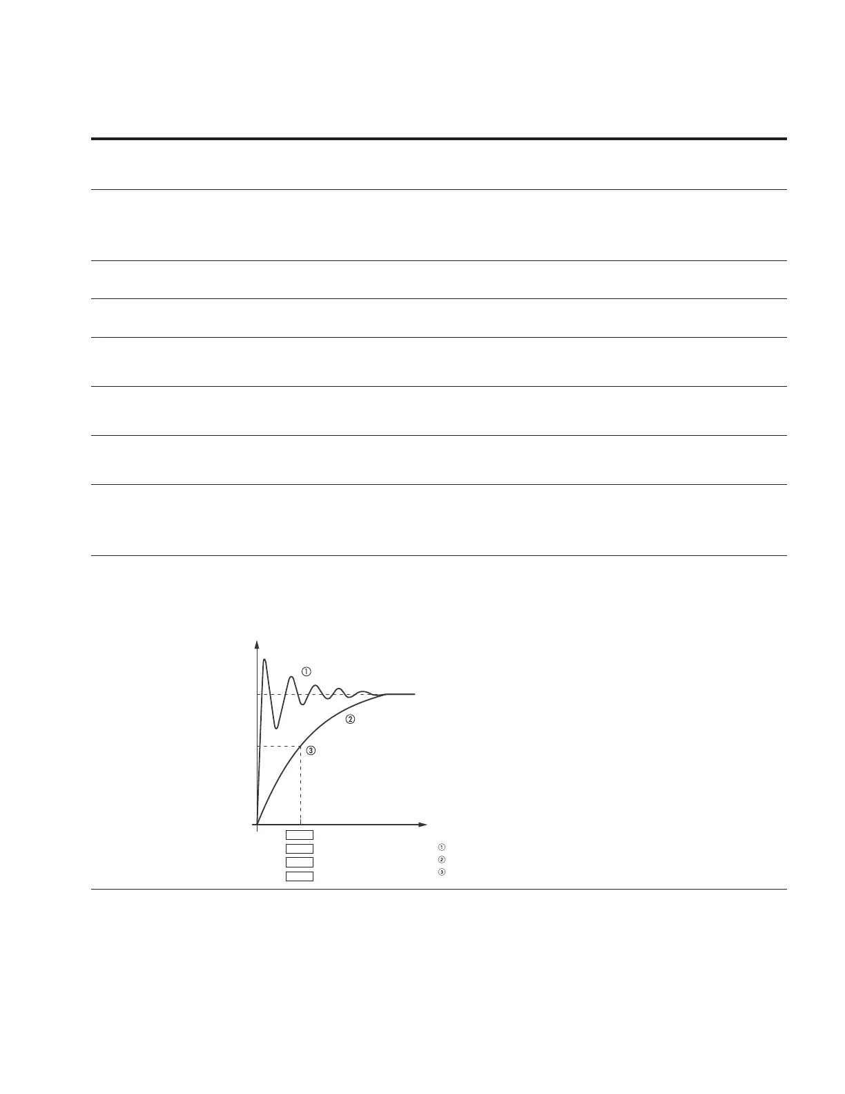
Figure 53. Analog output filtering
Notes
Analog signal with faults (unfiltered).
Filtered analog signal.
Filter time constant at 63% of the set value.
t (s)
100%
63%
AI
AO
P2.5
P2.15
P4.4
P4.11
AI1
AI2
AO1
AO2