164
Appendix A—Description of parameters
VARIABLE SPEED DRIVE SERIES III LIT-12012999—June 2018 www.johnsoncontrols.com
Code Modbus ID Parameter Application RO/RW
P4.1.9 2423 Run Delay Time 1,2,3 RW
Run Delay time parameter sets the time required for the drive to wait before another run command can
be received. During this time the run signal is given it is ignored until the time has expired upon which it
will then start, in keypad, I/O, or fieldbus Control Modes.
P4.1.10 252 Start Mode 1,2,3 RW
Use this parameter to define the start function.
Ramp
0 = The frequency converter starts from 0 Hz and accelerates to the set reference frequency within
the set acceleration time. (Load inertia or starting friction may cause prolonged acceleration times.)
Flying start
1 = The frequency converter is able to start into a running motor by applying a small voltage to motor
to search for the frequency corresponding to the speed the motor isrunning at. Searching starts from
the maximum frequency toward the actual frequency until the correct value is detected. Thereafter,
the output frequency will beincreased/decreased to the set reference value according to the set
acceleration/deceleration parameters.
Use this mode if the motor is coasting when the start command is given, with the flyingstart.
P4.1.11 253 Stop Mode 1,2,3 RW
Use this parameter to define the stop function.
Coasting
0 = The motor coasts to a halt without any control from the frequency converter, after the Stop
command, output of drive shuts off. The Motor slows based off the inertia loss.
Ramp
1 = After the Stop command, the speed of the motor is decelerated according to the set deceleration
parameters. If the regenerated energy is high and a faster deceleration is required, it may be necessary
to use an external braking resistor for faster deceleration.
Enabled Normal stop: Ramp/ Run
Disable stop: coasting
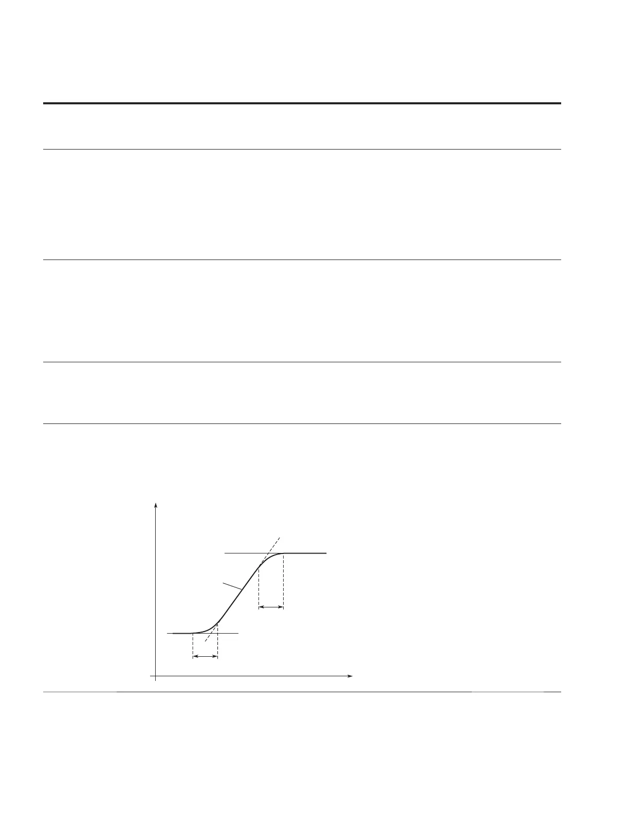
P4.1.12 247 Ramp 1 Shape 1,2,3 RW
Use this parameter to make the beginning and end of the acceleration and deceleration ramps can be
smoother. Setting a value of 0.0 gives a linear ramp shape that causes acceleration and deceleration to
react immediately to the changes in the reference signal.
Setting a value from 0.1 to 10 seconds for this parameter produces an S-shaped acceleration/
deceleration at the start and stop of the slope.
P4.1.13 248 Ramp 2 Shape 1,2,3 RW
The start and end of the acceleration and deceleration ramps can be smoothed with these parameters.
Setting a value of 0.0 gives a linear ramp shape that causes acceleration and deceleration to react
immediately to the changes in the reference signal.
Setting a value from 0.1 to 10 seconds for this parameter produces an S-shaped acceleration/
deceleration at the start and stop of the slope.
Figure 56. Acceleration/Deceleration (S-shaped)
P7.11 (P7.12)
P7.11 (P7.12)
P1.3, P1.4
(P7.13, P7.14)
t
Hz