170
Appendix A—Description of parameters
VARIABLE SPEED DRIVE SERIES III LIT-12012999—June 2018 www.johnsoncontrols.com
Code Modbus ID Parameter Application RO/RW
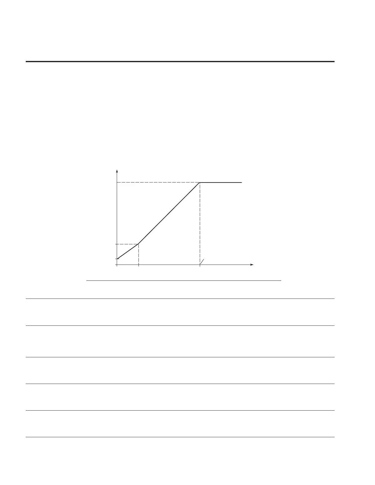
P5.1.4 108 2 = The V/Hz curve can be programmed with three different points. These points are the 0 frequency
voltage, midpoint and weakening point. A programmable V/Hz curve can be used if the other settings
do not satisfy the needs of the application. When running the Motor Identification this parameter
gets set by default along with the values below for the V/Hz curve along with the resistance
information of the motor.
Manual Motor Tuning - in Multi-Purpose App
1. Setting the Motor Magnetizing current:
• Run the Motor at 2/3 of the motor nominal frequency as the frequency reference.
• Read the Motor current in the Monitor Menu or via the InControl PC tool.
• Set the current as the Motor Excitation Current(Para ID775)
2. Set the V/Hz optimization parameter (Para ID108) to value 2 “Programmable V/Hz curve”.
3. Run the Motor with zero frequency reference and increase the motor zero point voltage (Para
ID293) until the motor current is approximately same as the motor Excitation Current. If the Motor
is in a low frequency area for only short periods, 65% of the motor nominal current is possible.
4. Set the Midpoint Voltage (Para ID292) to 1.4142*(Para ID293) and midpoint frequency(Para ID291)
to value Para ID291/100%*Para ID488.
5. If required, activate the speed control or V/Hz Optimization (Torque Boost).
6. If required, activate the speed control and V/Hz Optimization (Torque Boost).
Linear with flux optimization
1,2,3 RW
Figure 61. Programmable V/Hz curve
P8.8
(Default 100%)
P8.9
(Default 0%)
P8.7
(Default 5 Hz)
P8.5
U[V]
f[Hz]
Un
P8.6
Default: Nominal
Voltage of the Motor
Field Weakening
Point
Default: Nominal
Frequency of the
Motor
3 = The frequency converter starts to search for the minimum motor current in order to save energy,
lower the disturbance level and the noise.This function can be used in applications with constant
motor load, such as fans, pumps, etc.
P5.1.5 289 Field Weakening Point 1,2,3 RW
Use this parameter to set the frequency at which the output voltage reaches the field weakening point.
This value is usually determined by the motor nameplate value or if motor specs were supplied it can be
further adjusted.
P5.1.6 290 Voltage at FWP 1,2,3 RW
Use this parameter to set the voltage at the field weakening point as a percentage of the motor nominal
voltage. Above the frequency at the field weakening point, the output voltage remains at the set
maximum value. Below the frequency at the field weakening point, the output voltage depends on the
setting of the V/Hz curve parameters.
P5.1.7 291 V/Hz Mid Frequency 1,2,3 RW
Use this parameter if the programmable V/Hz curve has been selected, it defines the midpoint frequency
of the curve. This value can be set anywhere between 0 and the FWP, to either have a different V/Hz
ramp or if set to the FWP it will provide the max voltage all the way up the curve.
P5.1.8 292 V/Hz Mid Voltage 1,2,3 RW
Use this parameter if programmable V/Hz curve has been selected , it defines the mid point voltage of
the curve. This value can be set anywhere between zero frequency Volt and the FWP voltage, this can
either have a different ramp above and below this point or allow for max voltage.
P5.1.9 293 Zero Frequency Voltage 1,2,3 RW
Use this parameter if programmable V/Hz curve has been selected,it defines the zero frequency voltage
of the curve. When putting this value above 0% additional voltage is given, in some cases by putting this
value to high it can cause the motor to be oversaturated.