3. Press «Enter».
The menu for the selected measured value (in the example
p1
) is displayed.
4 0 0 m b a r 0 8 : 1 5 A M 8 0 ° C
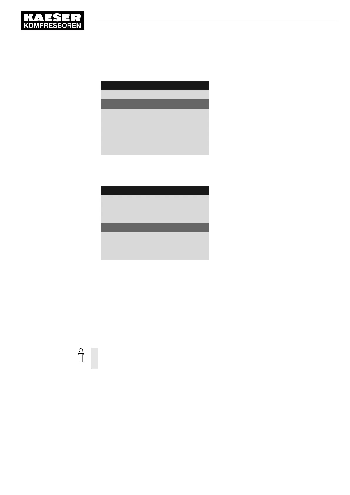
Header
5.10.3.1 p1
Menu
active: ☐
active line with check box
······························
SP: 0.40bar ¦ SD: 0.0bar
Switching point (SP) and switching differential (SD)
td 0s ¦ Logic +
Delay (td) and logic
DOR1.01 ☐
Output DOR
DOT1.01 ☐
Output DOT
8.8.3.1 Setting the switching point and switching differential
1. Use «Up» or «Down» to select the
SP
line.
4 0 0 m b a r 0 8 : 1 5 A M 8 0 ° C
Header
5.10.3.1 p1
Menu
active: ☐
······························
SP: 0.40bar ¦ SD: −0.2bar
Switching point (SP) and switching differential (SD)
td 0s ¦ Logic +
Delay (td) and logic
DOR1.01 ☐
Output DOR
DOT1.01 ☐
Output DOT
2. Press «Enter».
The display for the current threshold of the switching point flashes.
3. Use the «Up» or «Down» keys to set the
SP
threshold.
4. Press «Enter».
The setting is applied.
5. If necessary, adjust the value for the
SD
switching differential in the same way.
Result The threshold for the
SP
switching point and the
SD
switching differential are set.
8.8.3.2 Set the time delay
The delay can be set between 0 and 600 seconds. The delay is counted down from 600 in 1
second increments with the «DOWN» key and counted upwards from 0 (zero) in 1 second
increments with the «UP» key.
1. Use «Up» or «Down» to select the
td
line.
8 Initial Start-up
8.8 Setting input and output signals
No.: 901700 10 E
Service Manual Controller
SIGMA CONTROL 2 BLOWER ≥ 2.5.3
127

 Loading...