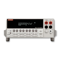
1 Option slot
An optional scanner card (Model 2000-SCAN or 2001-TCSCAN) installs in this slot.
2 Input connections
INPUT HI and LO Used for making DC volts, AC volts, two-wire resistance
measurements, and for connecting scanner card.
SENSE Ω4 WIRE Used with INPUT HI and LO to make four-wire resistance measure-
HI and LO ments, for connecting scanner card, and RATIO measurements in
conjunction with INPUT HI and LO.
3 TRIGGER LINK
One eight-pin micro-DIN connector for sending and receiving trigger pulses among other
instruments. Use a trigger link cable or adapter, such as Models 8501-1, 8501-2, 8502, 8503.
4 RS-232
Connector for RS-232 operation. Use a straight-through (not null modem) DB-9 shielded
cable.
5 IEEE-488
Connector for IEEE-488 (GPIB) operation. Use a shielded cable, such as Models 7007-1 and
7007-2.
6 Power module
Contains the AC line receptacle, power line fuse, and line voltage setting. The Model 2010
can be configured for line voltages of 100V/120V/220V/240VAC at line frequencies of 45Hz
to 66Hz or 360Hz to 440Hz.
7,8 Digital Common
Basic Measurements 2-7

 Loading...