Kinco FD5P AC series servo driver
Chapter 3 Installation and wiring
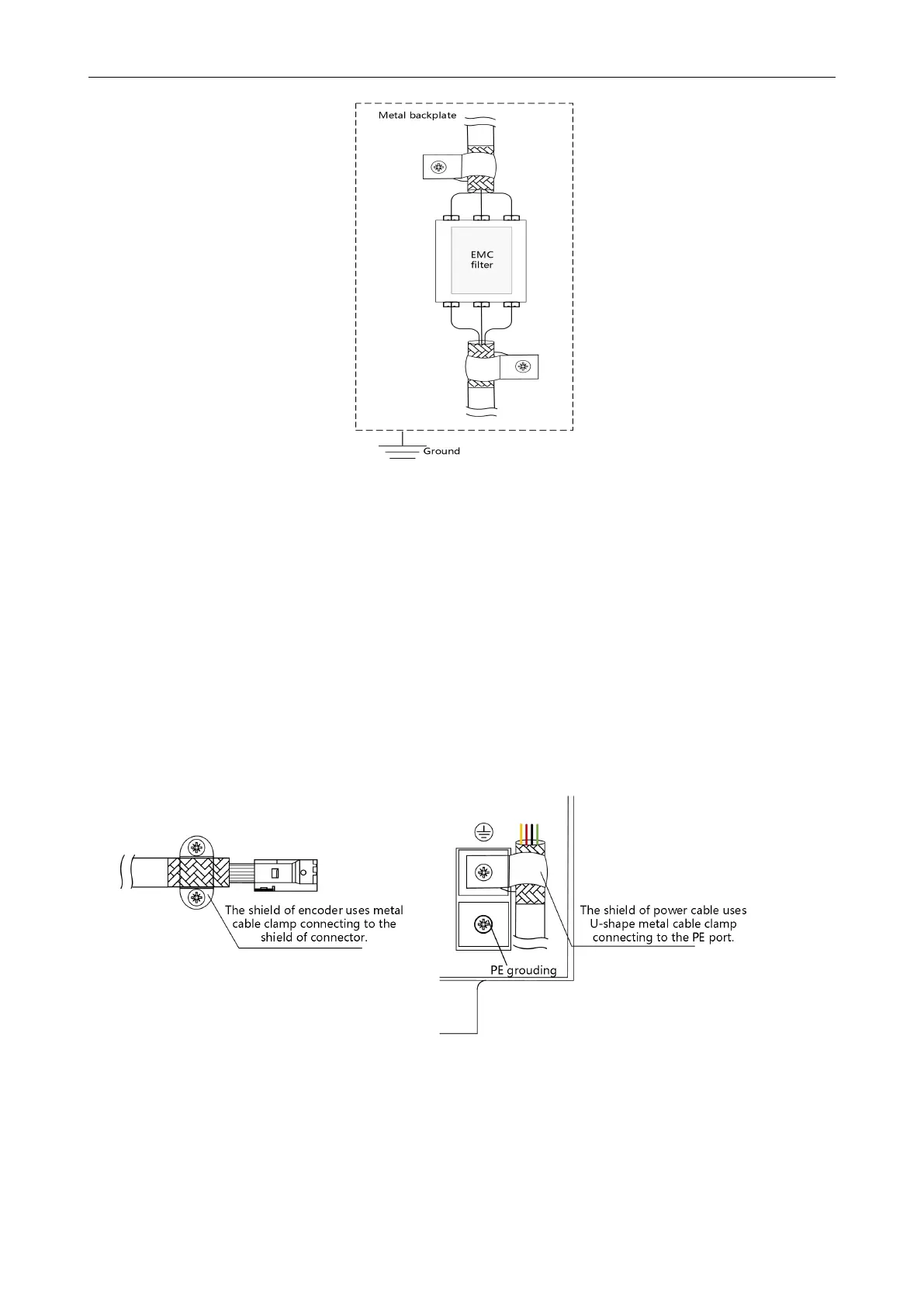
Figure 3-6 EMC noise filter installation diagram
(3) Shielded layer
Input and output signal cables, power cables, encoder cables and communication cables please use
shielded cables.
The shield of the encoder is clamped to the connector metal housing using metal cables.
The shielding layer near the driver side of the power cable is locked to the driver PE screw using the
U-shaped metal clip delivered with the product.
If the power line and the encoder are not direct outlet solutions, it is necessary to peel the sheath
layer at both ends of the connector and connect the shielded layer of the cable to the metal plate
using a 360-degree shield clamp.
Figure 3-7 Driver side power line/encoder line shield layer 1* processing mode
 Loading...

