Kinco FD5P AC series servo driver
册
Chapter 6 Operation modes and control modes
Table 6-2 Digital function output
0001: Ready
0002: Error
0004: Pos Reached
0008: Zero Speed
0010: Motor Brake
0020: Speed Reached
0040: Index signal occurrence
0080:Maximum speed limit achieved
in torque mode
0100:Motor lock shaft
0200: Position Limit
0400: Home Found
0800:Torque reach set
1000:Multi-function signal 0
2000:Multi-function signal 1
4000:Multi-function signal 2
9001: PosTable Active
Table 6-3 Polarity setting
Table 6-4 Digital input and output signal polarity and simulation setting method
input/output port
0
:
output
1
:
input
Channel
input
:
1-7
output:1-5
0
:
input and output ports are normally closed
1
:
input and output ports are normally closed
Other than 0 or 1
:
check the current situation
。
Input/output port
0:output
1
:
input
Channel
input:1-7
output
:
1-5
0:no simulate signals, it will not force output of valid signal
1
:
simulate signals, it will force output of valid signal
Other than 0 or 1: check the current situation。
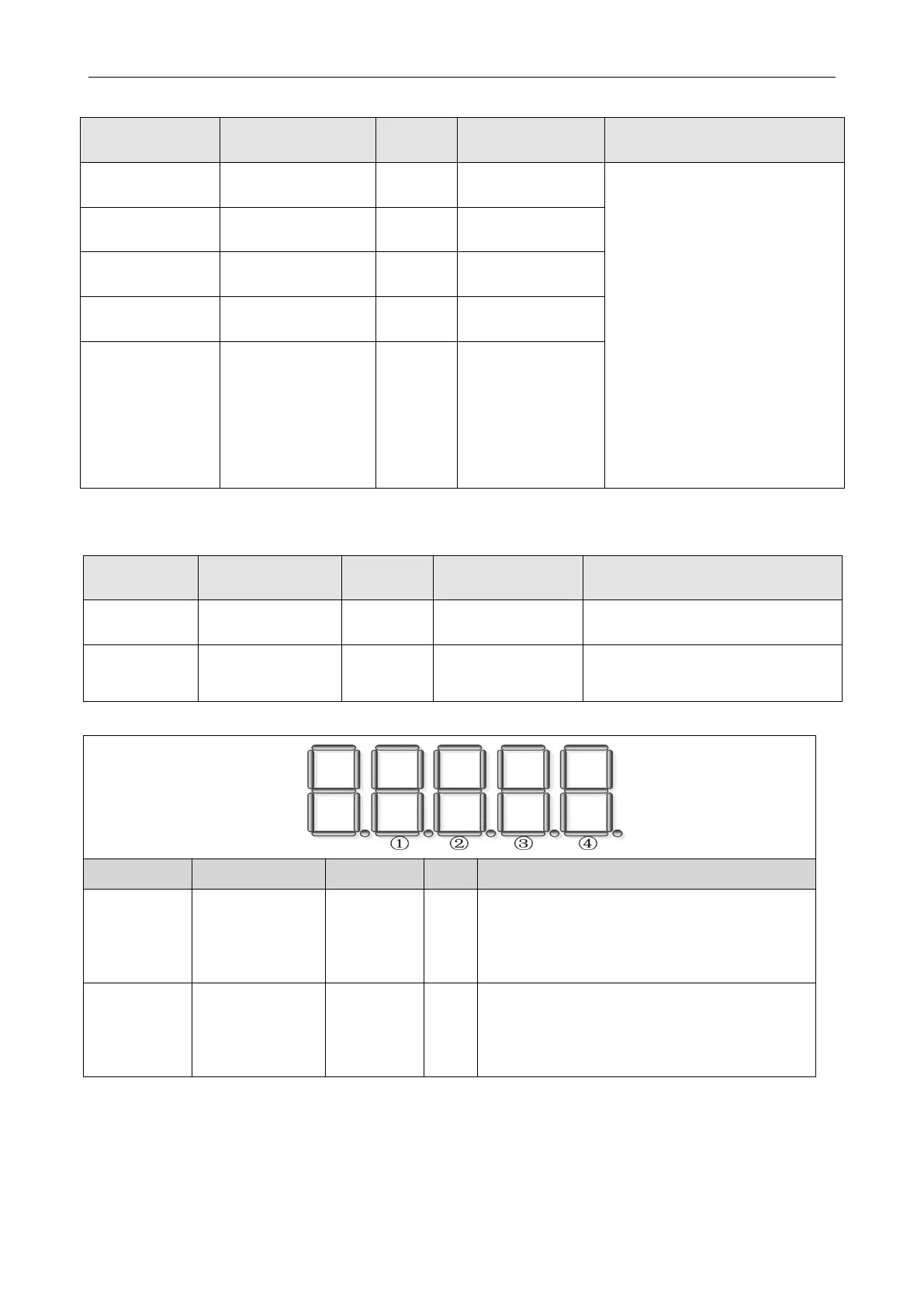
Example: setting d3.08 to "110.0" means that the DIN1 input port is a normally closed
point, and setting d3.08 to "110.1" means that the DIN1 input port is a normally open
point. Setting d3.09 to "110.0" means not to simulate the DIN1 input signal, and setting
d3.09 to "110.1" means to simulate the DIN1 input signal.
Used to simulate the input signal and force
the output of a valid signal
 Loading...

