LABORIE Goby Owner’s Manual GOBY-UM02 19
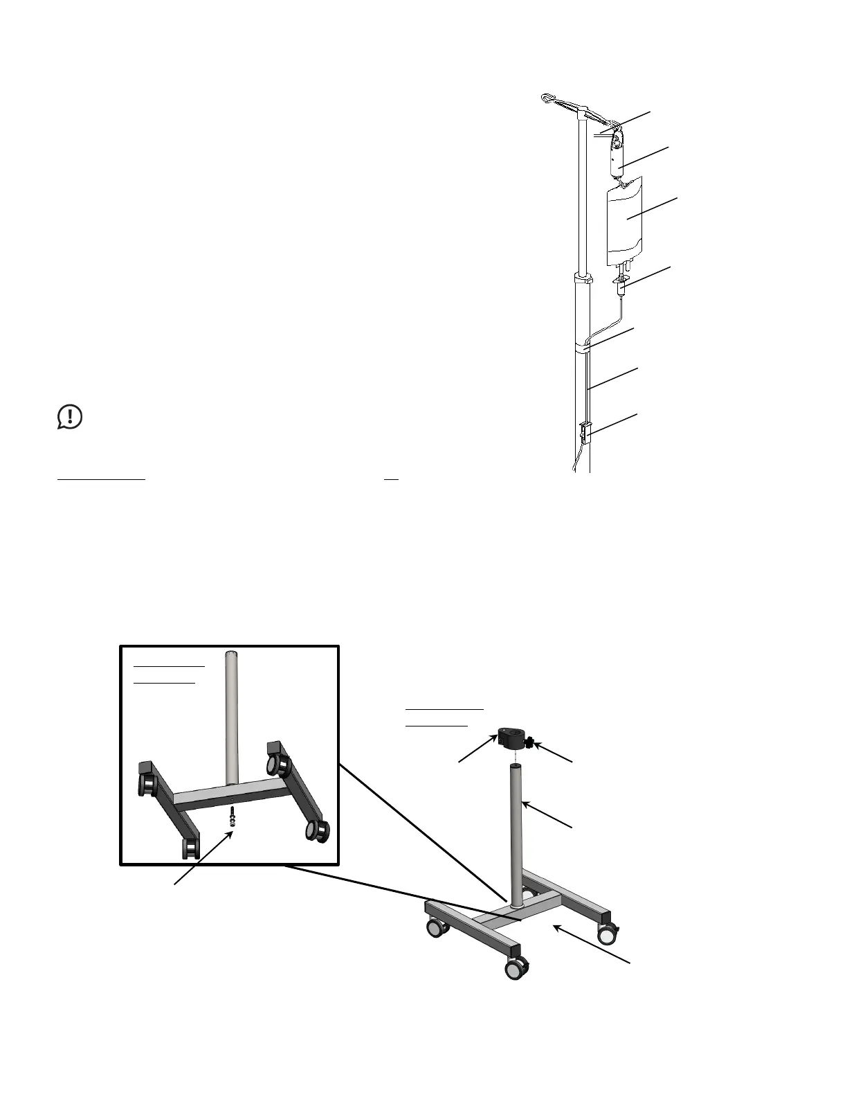
3.2.6 Set up Infusion Transducer (optional)
To set up the infusion transducer follow the instructions provided
below. Refer to Figure 10 for a representation of completed set-up.
1. Place the infusion transducer on the IV pole.
2. Connect the infusion transducer cable to the circular-shaped
connector at the bottom of the
Hub.
3. Place a 1000 ml bag of sterile saline inside a pressure cuff.
Hang the pressure cuff on the hook of the infusion transducer.
LABORIE recommends the positioning of the IV pole at least
30 cm above the patient table.
4. Inflate the pressure cuff to 300 mm Hg (when the green line
appears on the pressure cuff gauge).
5. Connect an infusion line to the saline bag. Use a basic solution
set with a drip chamber.
6. Tape the infusion line to the IV pole between the drip chamber
and the roller clamp (flow control valve). Ensure there is excess
tubing between the tape and the drip chamber. If the tubing is
pulled tight then it will produce inaccurate readings. Connect
the other end of the infusion line to the filling port on the
catheter.
: The infusion transducer is calibrated for up to 1000 ml of
sterile saline or water. Re-calibration is required for use of different mediums
such as hypaque. See the
Calibrate the Infusion Transducer section on page 92
for information on
calibrating the Infusion Transducer.
Figure 10: Infusion Transducer Setup
3.2.7 Assemble the Puller Stand (Optional)
To assemble the Puller Stand (UPP1006), prepare one 6mm and one 4mm HEX L-KEY.
1. Connect the Pole Assembly to the H-Base Assembly using the provided Washer M8, Split Washer M8, and Screw
M8. Use the 6mm HEX L-Key to secure the screw (Figure 11).
2. Slide the Clamp Assembly into the post of the Puller Base Assembly and lock it in position with the Knob Screw
provided. Use a 4mm Hex L-Key to insert the Puller into the Clamp Assembly (Figure 11).
Figure 11: Puller Base and Puller Stand Assembly
SALINE BAG
Split Lock Washer, M8
Assembly
 Loading...