LABORIE Goby Owner’s Manual GOBY-UM02 84
6.4 AMBULATORY MONITORING
The Ambulatory Monitoring feature allows the UDS Roam™ to monitor pressure and EMG data separate from the software
once setup. The
UDS Roam™ will store information while the test is recording, at completion of test the data must be
downloaded into the software for analysis.
NOTE: The UDS Roam™ can run for 1 voiding cycle (3 hours) or 2 to 3 voiding cycles (4 to 6 hours). Fully charge the
UDS Roam™ and calibrate the remote control buttons.
IMPORTANT: The Ambulatory Monitoring feature is available for remote ambulatory users only.
6.4.1 Setting Up the Remote Control and UDS Roam for Ambulatory Testing
Use the remote control to add events to the graph during tests. Once the buttons are configured click the button as the
events occur and they will be recorded on the graph. Press and hold the configured buttons for at least 1 second.
6.4.1.1 Part 1: Calibrate P4
1. Plug the Ambulatory Remote into Channel 4 (P4) of the UDS Roam™.
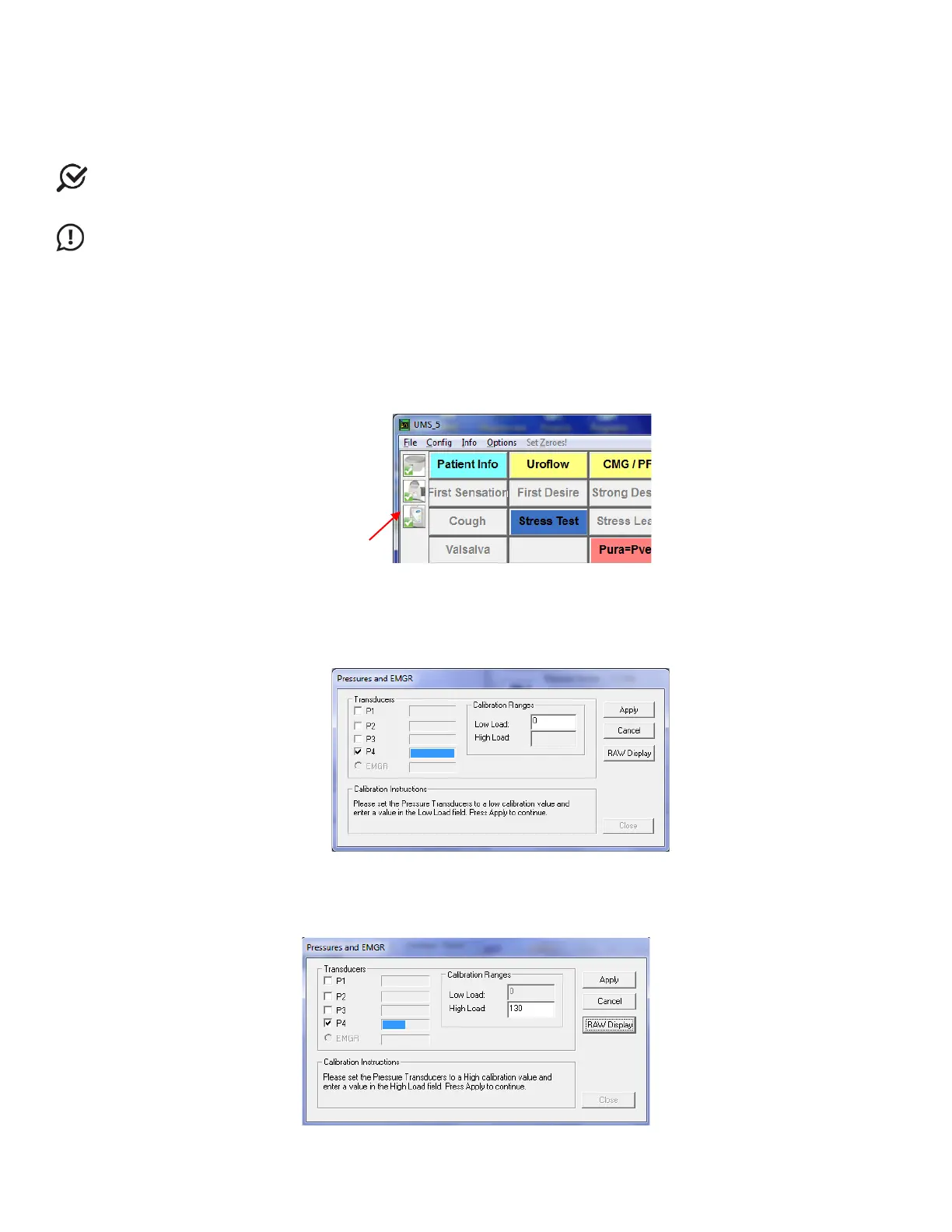
2. Double-click the UDS Roam icon in the main window to open the Goby Device Manager window:
Figure 95: Goby Device Manager Window – Calibrate Remote Control and UDS Roam
3. Click the Setup button to launch the Setup window. Click the Device Calibration button.
4. Select P4 for calibration as the Ambulatory Remote connects to channel 4 of the UDS Roam™.
5. Type 0 into the Low Load box and click the Apply button (Figure 96).
NOTE: do not press any event buttons on the remote.
Figure 96: Device Calibration – Pressures and EMGR Window
6. Click the RAW Display button. Press each button on the remote control and make note of the button that
has the lowest RAW value when pressed.
NOTE: The button with the lowest RAW value is usually button 6.
7. Type 130 in the High Load box (Figure 97).
Figure 97: Device High Load Calibration – Pressures and EMGR Window