LABORIE Goby Owner’s Manual GOBY-UM02 39
• To change the scale units, click the Units box of a channel and then click the down arrow beside the Units
combo box to select the desired unit.
• Math Channels can be used to perform arithmetic operations between one or more channels. The math
channels support basic arithmetic operations (e.g. addition, subtraction, multiplication and division) and the
parenthesis operator.
• VBN feature allows for the overlay of Normal Flow Match information. Utilize the CALQ Math Channel to
overlay VBN information (Normal Flow Match) over the flow channel.
• To change the channel color, double-click the box under the Curve Appearance column and select the new
color in the Color dialog box. Click
OK when selected.
• Display Line Width feature allows the user to make the channel curve thicker (in pixels) on the display. Click the
box under the Display Line Width column of the test channel and type the desired display line width in pixels.
• Print Line Width feature allows the user to make the channel curve thicker (in pixels) on the printout only. Click
the box under the Print Line Width column of the test channel and type the desired Print Line Width in pixels.
• Symmetry feature allows the user to mirror a channel’s curve making a negative mirrored curve. Click the box
under the
Symmetry column for the selected channel and select Mirrored or Simple.
• Interior feature allows the user to fill the area under the curve with the same color as the channel background
color.
• The Printable option allows the user to see the graph curves on the test results printout. Select
Printable
to
include the curve in a printout.
• Curve Overlay allows the user to display up to 5 channel curves on the same graph on the display and print out.
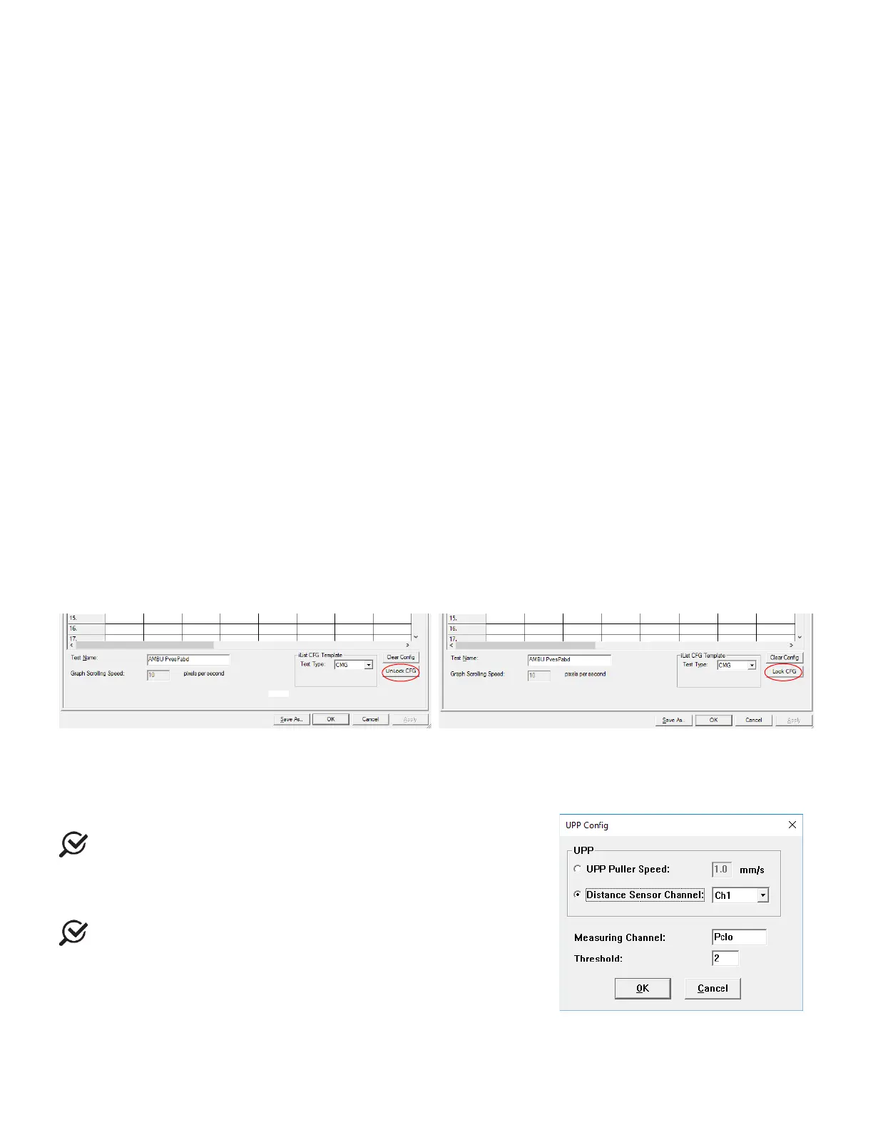
Unlock CFG in Channel Settings
To aide in the prevention of accidental overwriting of test configuration the software provides a lock/unlock function in the
Configuration window.
IMPORTANT: All configuration files provided in the UDS120 software are locked at installation. Only unlock if you are sure
of the modifications required.
Click Config > Set up/Modify to open the configuration file list and select a configuration file that needs modification.
Click the
Unlock CFG button. Click Yes in the resulting warning message to continue. Make changes as needed and when
complete click the
Lock CFG button. Click Yes in the resulting warning message to lock the configuration file (Figure 39).
Figure 39: Lock and Unlock CFG
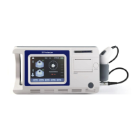
5.5.3.2 UPP Tab
Under the UPP configuration tab set the UPP Puller speed or calculate the UPP Distance Summary based on the distance a
catheter is pulled with an attached sensor.
1.
Connect the Distance Sensor/Catheter to Ch1.
Make sure the Sensor has been calibrated first.
2. Select the Distance Sensor Channel option (Figure 40).
3. Select Ch1 from the listing.
4. Click
.
Make sure you first select the
test button on the Control
Panel before setting up this feature.
Figure 40: UPP Configuration Window