4. Parameters
4-44
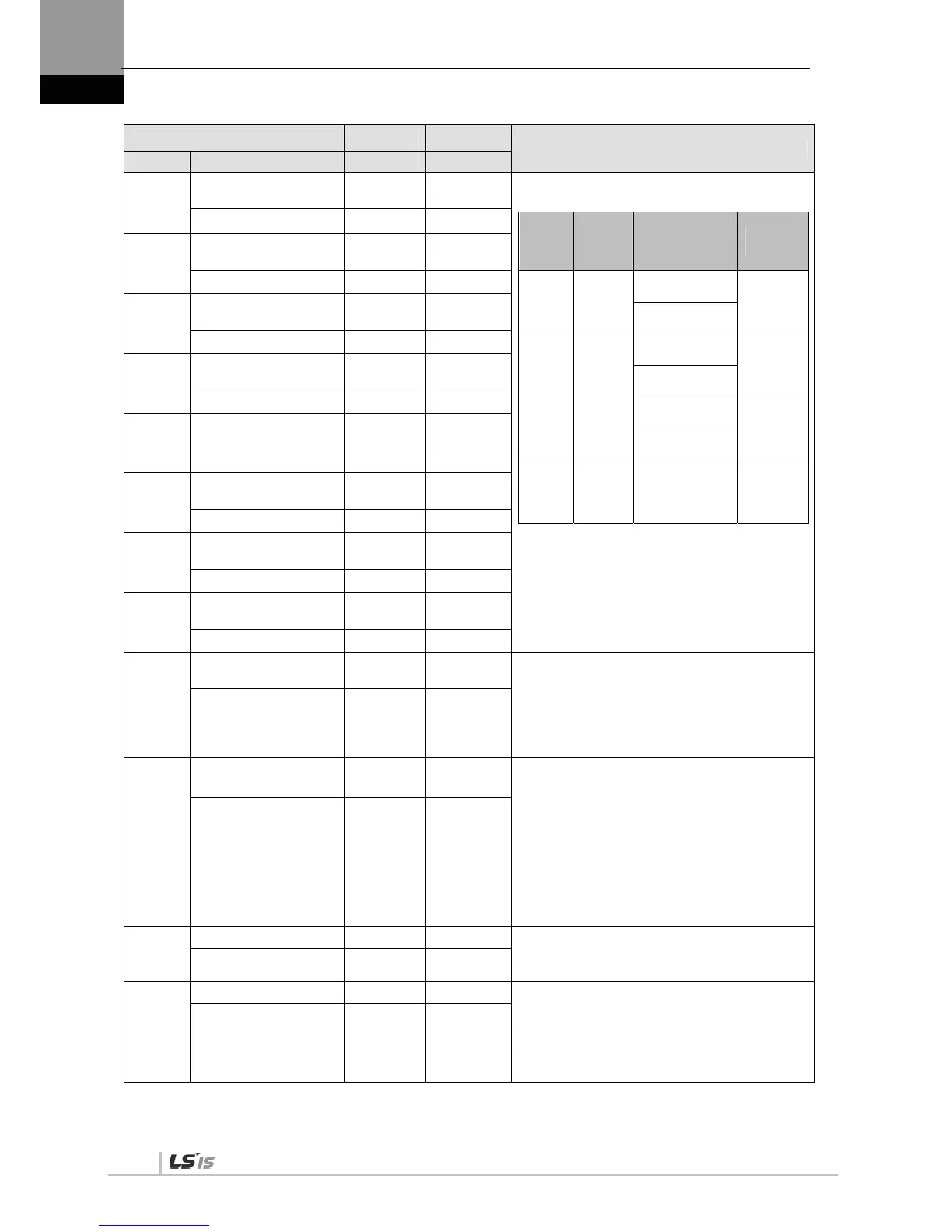
Parameter Unit Initial
Details
Code Name Minimum Maximum
*P4-01
Electronic gear ratio
numerator 1
- 1000
Sets electronic gear ratio numerator/denominator 1,
2, 3, and 4.
EGEAR
1
EGEAR
2
Electronic Gear
Ratio
Numerator /
Denominator
Electronic
Gear Ratio
OFF OFF
Electronic gear
ratio numerator 1
Electronic
gear ratio 1
Electronic gear
ratio denominator 1
ON OFF
Electronic gear
ratio numerator 2
Electronic
gear ratio 2
Electronic gear
ratio denominator 2
OFF ON
Electronic gear
ratio numerator 3
Electronic
gear ratio 3
Electronic gear
ratio denominator 3
ON ON
Electronic gear
ratio numerator 4
Electronic
gear ratio 4
Electronic gear
ratio denominator 4
The electronic gear ratio is the
numerator/denominator form of the relation
between the position command input pulse and
the motor encoder pulse. It is important to set
the ratio so that there is no error during position
operation.
(Details: Refer to “4.4.6 Position Operation
Parameter Setting.”)
Electric gear num.1
1 2^21
*P4-02
Electronic gear ratio
numerator 2
- 1000
Electric gear num.2
1 2^21
*P4-03
Electronic gear ratio
numerator 3
- 1000
Electric gear num.3
1 2^21
*P4-04
Electronic gear ratio
numerator 4
- 1000
Electric gear num.4
1 2^21
*P4-05
Electronic gear ratio
denominator 1
- 1000
Electric gear den.1
1 32767
*P4-06
Electronic gear ratio
denominator 2
- 2000
Electric gear den.2
1 32767
*P4-07
Electronic gear ratio
denominator 3
3000
Electric gear den.3
1 32767
*P4-08
Electronic gear ratio
denominator 4
- 4000
Electric gear den.4
1 32767
P4-09
Electronic gear ratio
mode
- 0
Select an electronic gear ratio mode.
0: Select electronic gear ratio 1-4.
1: Override offset [P4-10] on the electronic gear
ratio numerator 1.
(Details: Refer to “4.4.6 Position Operation
Parameter Setting.”)
Electric gear mode 0 1
P4-10
Electric gear ratio
numerator offset
- 0
Sets the offset of the electronic gear ratio numerator
1.
The offset will be set on the electronic gear ratio
numerator 1.
EGEAR1 contact LOW -> HIGH
: Increase as the [P4-10] setting value .
EGEAR2 contact LOW -> HIGH
: Decrease as the [P4-10] setting value .
(Details: Refer to “4.4.6 Position Operation
Parameter Setting.”)
Electric gear num.
offset
-32767 32767
P4-11
Position error [Pulse] 90000 Sets range for triggering the position error alarm.
(Details: Refer to “4.4.4 Input/Output Contact
Parameter Setting.”)
Following error range 1 2^30
P4-12
Limit contact function - 0 Select the operation type of position command pulse
clear for CWLIM and CCWLIM contacts.
0: Ignore any input pulses when the CCWLIM /
CWLIM contact is on.
1: When the CCWLIM / CWLIM contact is on,
receive an input pulses and save them to buffer.
Position limit
function
0 1

 Loading...
