4. Parameters
4-66
4.4.6 Position Operation Parameter Setting
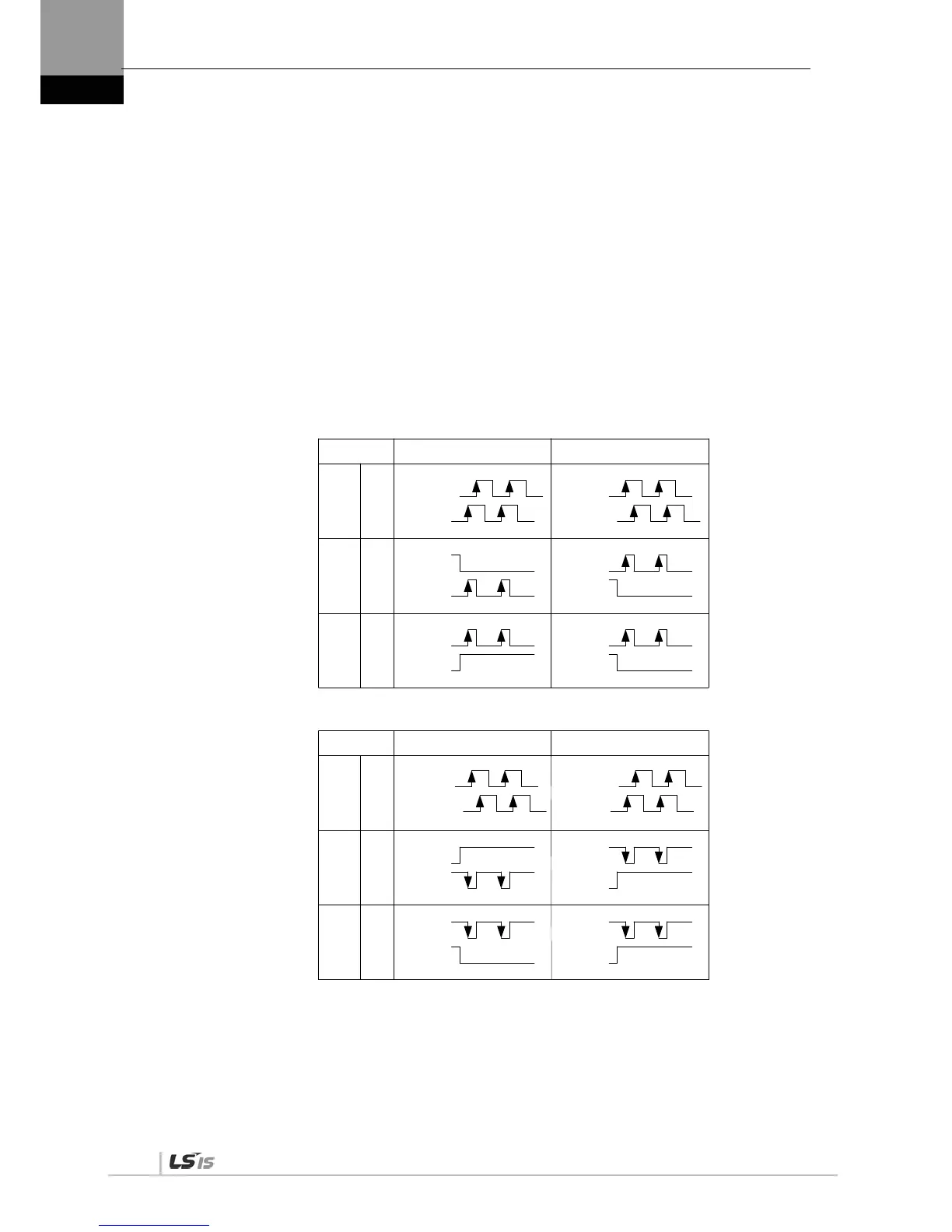
(1) Input Pulse Logic [P4-00]
Set type of the position command input pulse and rotation method per logic.
0: A+B
1: CW+CCW, positive logic
2: Pulse + sign, positive logic
3: A+B
4: CW + CCW, negative logic
5: Pulse + sign, negative logic
PULS
(CN1-9)
SIGN
(CN1-11)
PULS
(CN1-9)
SIGN
(CN1-11)
0
1
Phase
A + B
Positive
Logic
CW+CCW
Positive
Logic
PULS
(CN1-9)
SIGN
(CN1-11)
2
Pulse +
direction
positive
logic
Forward rotation Reverse rotation
PULS
(CN1-9)
SIGN
(CN1-11)
PULS
(CN1-9)
SIGN
(CN1-11)
PULS
(CN1-9)
SIGN
(CN1-11)
PF + PR
L Level
L Level
L Level
H Level
PULS
(CN1-9)
SIGN
(CN1-11)
PULS
(CN1-9)
SIGN
(CN1-11)
3
4
PULS
(CN1-9)
SIGN
(CN1-11)
5
Forward rotation
Phase
A + B
Negative
Logic
CW+CCW
Negative
Logic
Pulse +
direction
negative
logic
Reverse rotation
PULS
(CN1-9)
SIGN
(CN1-11)
PULS
(CN1-9)
SIGN
(CN1-11)
PF + PR
PULS
(CN1-9)
SIGN
(CN1-11)
H Level
H Level
H Level
L Level

 Loading...
