2. Installation
2-5
2.2.3 Power Wiring
Make sure that the input power voltage is within the allowed range.
Caution
Overvoltage can damage the drive.
Connecting commercial power to the U, V and W terminals of the drive may cause damage.
Be sure to supply power via L1, L2 and L3 terminals.
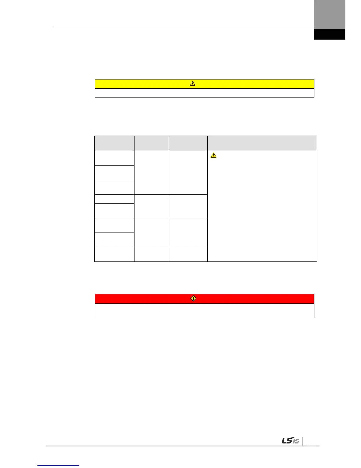
Connect short-circuit pins to the B and BI terminals. For external regenerative resistance, use
standard resistance for the B+ and B terminals after removing the short-circuit pins.
Model
Resistance
Value
Standard
Capacity
* Notes
XDL-
L7A001
100 [] Built-in 50 [W]
Caution
For more information about resistance for
expanding regenerative capacity, refer to “7.3
Option and Peripheral Device.”
XDL-
L7A002
XDL-
L7A004
XDL-L7A08
40 []
Built-in 100
[W]
XDL-
L7A010
XDL-
L7A020
13 []
Built-in 150
[W]
XDL-
L7A035
XDL-
L7A050
6.8[] Built-in 120[W]
Configure the system in a way that main power (L1, L2, L3) is supplied only after control power (C1,
C2). (Refer to “Chapter 3 Wiring.”)
High voltage remains for a while, even after the main power is disconnected.
Danger
After disconnecting the main power, make sure that the charge lamp is off before you start
wiring. There is a risk of electric shock.
Grounding must be done over the shortest distance.
A long ground wire is susceptible to noise which may cause malfunction.

 Loading...
