3. Wiring Method
3-23
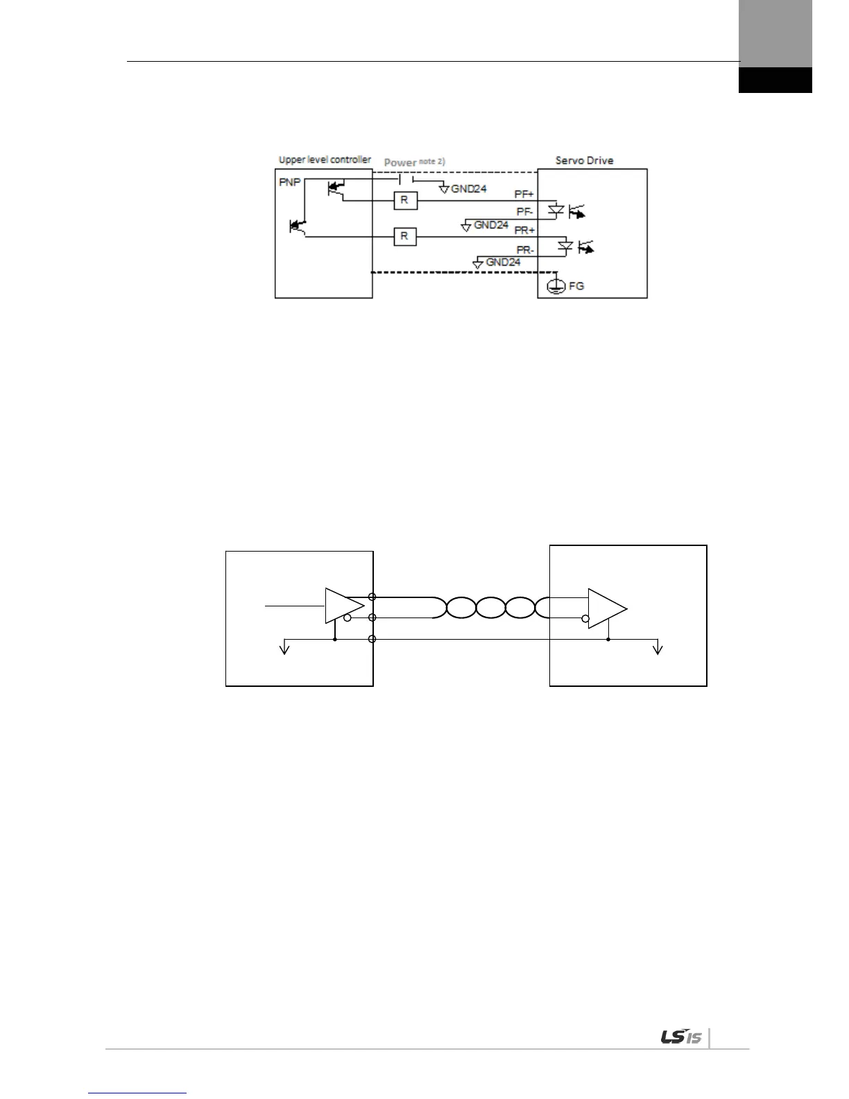
(4) PNP Open Collector Pulse Command
NOTE 1) When using 24 [V] power: Resistance R = 1.5 [k], 1/2 [W]
When using 12 [V] power: Resistance R = 560-680 [], 1/2 [W]
When using 5 [V] power: Resistance R = 100-150 [], 1/2 [W]
3.5.5 Encoder Output Signal
Connect the GND terminal of the upper level controller and the GND terminal of CN1
because encoder signals are output based on the GND of control power.
Encoder signals for the servo motor received from CN2 are pre-scaled, according to the ratio
defined by [P0-14] and output in line driver mode.
Set “1” on the 3
rd
bit in the menu [P0-17] ‘Function Select Bit',
It outputs open collector A,B,Z phases through existing AL0, AL1 and AL2 contact points.
(Output voltage 40mA and below, Maximum frequency 100Khz)
Servo Drive
Upper level controller
P

 Loading...
