4. Parameters
4-56
1 : 0~+10V
DIGIT 5 -> Sets EEPROM save function in communication.
0: EEPROM use.
1: EEPROM not for use
17. DAC output setting
There are 2 kinds of DAC output, each of which is made every 200 [usec] according to the condition
of used data.
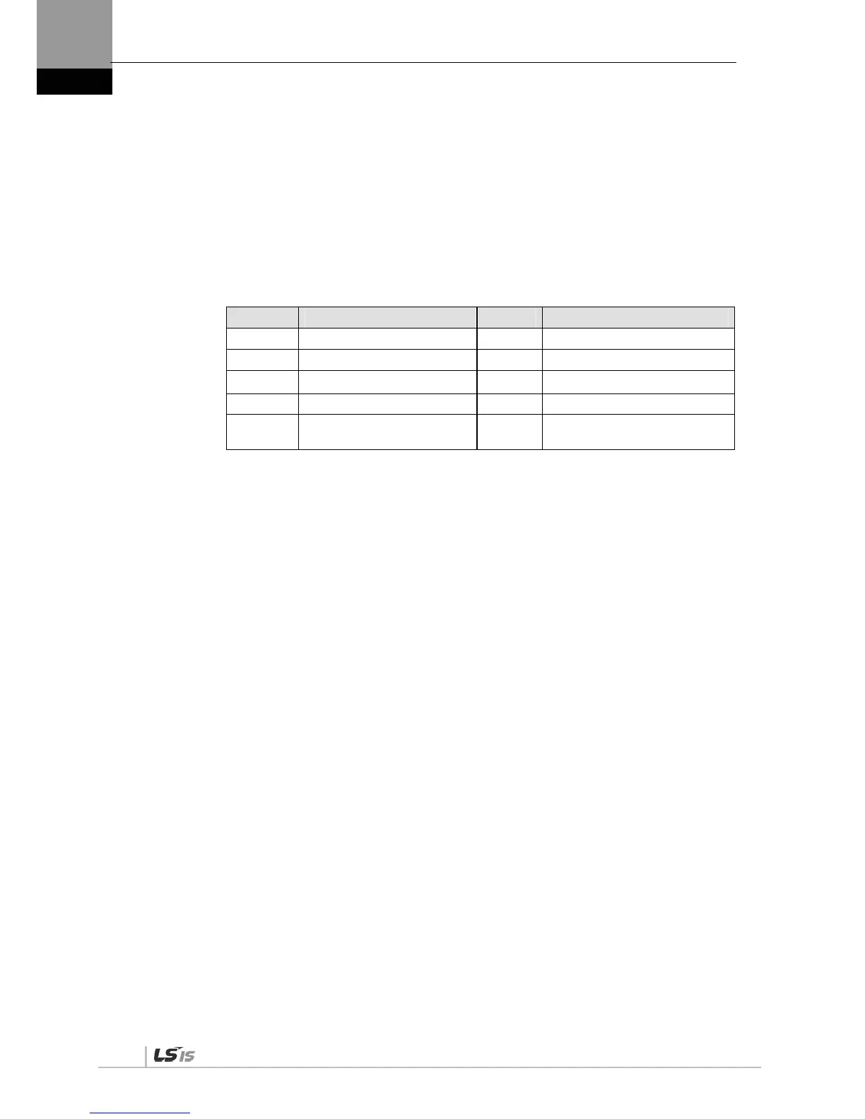
DAC output type [P0-18 DIGIT 1, DIGIT 2]
Type Data Content Type Data Content
0 Speed feedback [RPM] 5 Following error [pulse]
1 Speed command [RPM] 6 DC link voltage [V]
2 Torque feedback [%] D Speed command (user) [RPM]
3 Torque command [%] E Torque command (user) [%]
4
Position command frequency
[0.1 Kpps]
DAC output scale[P0-23], [P0-24]
If the output value is too low or too high, output ratio can be adjusted.
Sets magnification [Unit/V] for analog output channels 1 and 2.
(Speed [RPM], torque [%], position command frequency [0.1 Kpps], position [pulse], DC link [V])
Example) Channel 1 scale 100 =>100 [RPM] is output as 1 [V].
DAC output offset [P0-19], [P0-20]
Sets offset [Unit/V] for 1 ~ 2 analog output channels.
(Speed [RPM], torque [%], position command frequency [0.1 Kpps], position [pulse], DC_Link
[V])
4.4.2 Control Parameter Setting
The order of setting control parameters is as follows:
Load inertia ratio [P1-00] setting: Refer to “5.2.6 Auto Gain Tuning [Cn-05].”
Position proportional gain [P1-01] and [P1-02] adjustment:
Increase the gain to the extent that the servo motor does not overshoot or take off (do not use
during speed operation or torque operation).
Speed proportional gain [P1-06] and [P1-07] adjustment:
Increase the gain to the extent that the servo motor does not vibrate.
Speed integral time constant [P1-08] and [P1-09] adjustment:
Refer to the following table and perform setting according to the speed proportional gain.

 Loading...
