3. Wiring Method
3-5
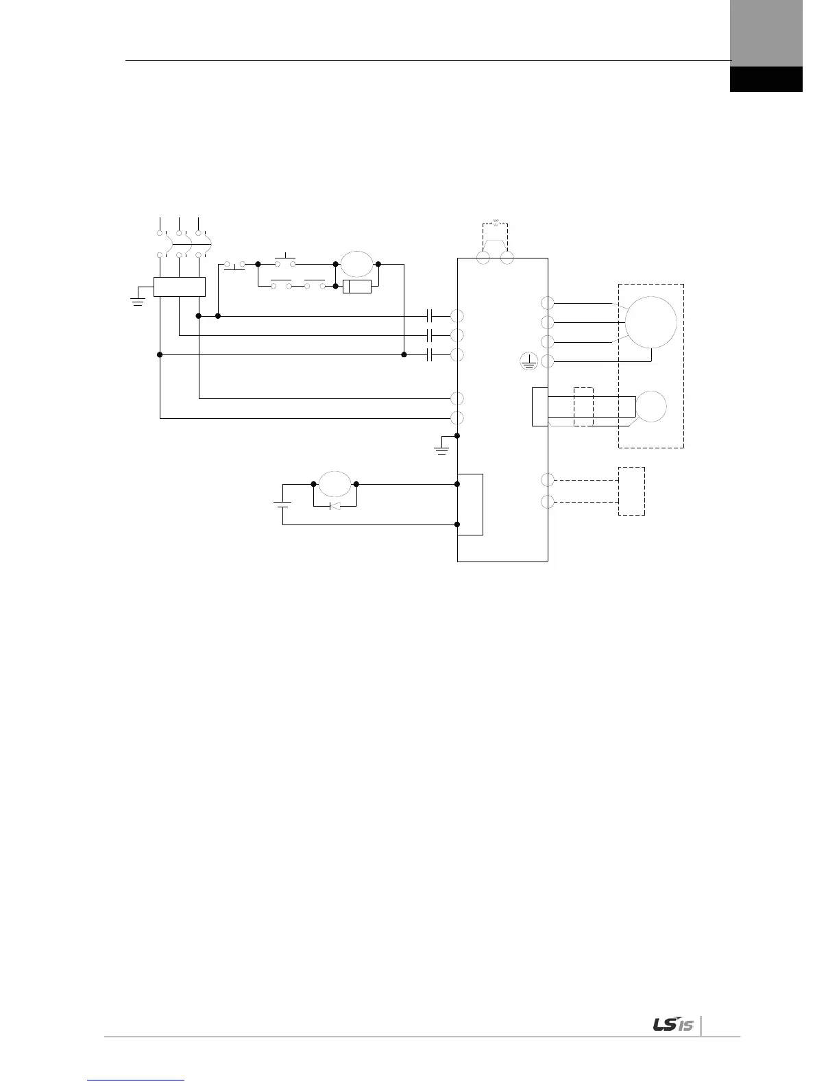
3.2.2 XDL-L7 Drive Wiring Diagram [XDL-L7SA050□]
U
V
W
L1
L2
L3
C1
C2
B+
B
38
39
CN1
RA
M
E
Alarm-
Alarm+
1Ry
RA
1SK
1Ry1MC
+24V
NF
1MC
RST
(200~230V)
Main
OFF
Main
ON
Encoder
(Note1)
(Note2)
PO
PI
DC Reactor
external
regenerative
resistance
Servo Drive
NOTE 1) It takes approximately one to two seconds until alarm signal is output after you turn on the main
power. Accordingly, push and hold the main power ON switch for at least two seconds.
NOTE 2) Check status of connection of internal regenerative resistance (B+, B) before using because XDL-
L7SA050 (120[W], 6.8[]) has internal regenerative resistance. If the value of regenerative
voltage is too high by frequent deceleration and acceleration, install external regenerative
resistance on B, B+ terminal after attaching internal regenerative resistance connected B+, B to
“NC” hole on the case.

 Loading...
