6. Communication Protocol
6-16
6.3.4 Input/Output Parameter Communication
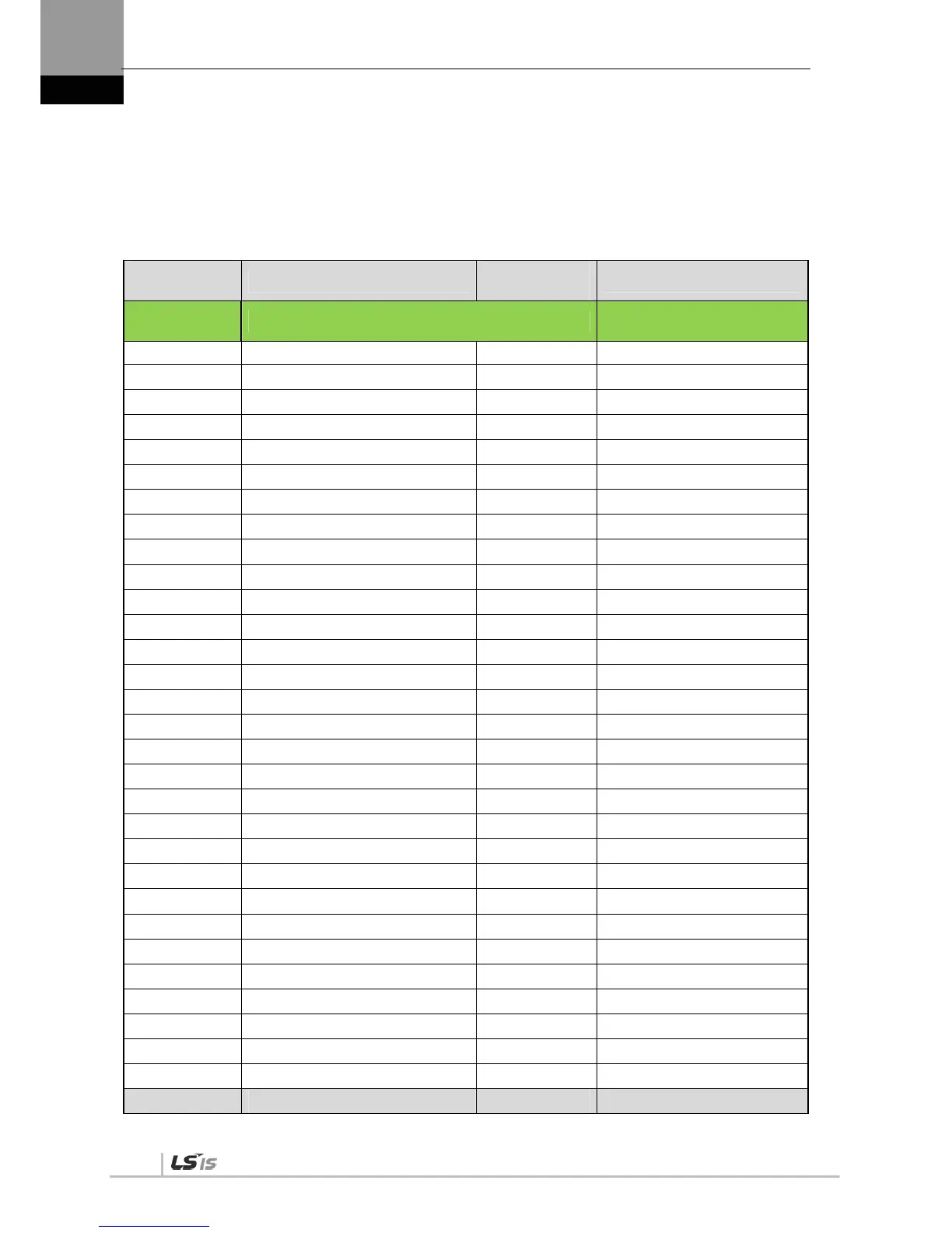
Address Table
The following table lists Modbus communication addresses for the input/output parameter
(analog and digital) parameter group [P2-xx].
Communicatio
n Address
Parameter Name
Parameter
Number
Material Type
(Decimal
Number)
Input/Output Parameter Parameter
220 Input signal definition 1 P2 - 00 UINT16
222 Input signal definition 2 P2 - 01 UINT16
224 Input signal definition 3 P2 - 02 UINT16
226 Input signal definition 4 P2 - 03 UINT16
228 Input signal definition 5 P2 - 04 UINT16
230 Output signal definition 1 P2 - 05 UINT16
232 Output signal definition 2 P2 - 06 UINT16
234 Output signal definition 3 P2 - 07 UINT16
236 Input signal logic definition 1 P2 - 08 UINT16
238 Input signal logic definition 2 P2 - 09 UINT16
240 Output signal logic definition P2 - 10 UINT16
242 Range of output for position reached P2 - 11 UINT16
244 Zero speed output range P2 - 12 UINT16
246 Range of output for speed reached P2 - 13 UINT16
248 Brake output operation speed P2 - 14 UINT16
250 Brake output delay time P2 - 15 UINT16
252 Position pulse clear mode P2 - 16 UINT16
254 Analog speed command scale P2 - 17 UINT16
256 Analog speed command offset P2 - 18 INT16
258 Zero speed clamp speed P2 - 19 UINT16
260 Analog torque command scale P2 - 20 UINT16
262 Analog torque command offset P2 - 21 INT16
264 Zero speed clamp voltage P2 - 22 UINT16
266 Reserved
268 Reserved
270 Reserved
272 Reserved
274 Reserved
276 Reserved
278 Reserved

 Loading...
