6. Communication Protocol
6-10
6.3 XDL-L7 Servo Drive Communication
Address Table
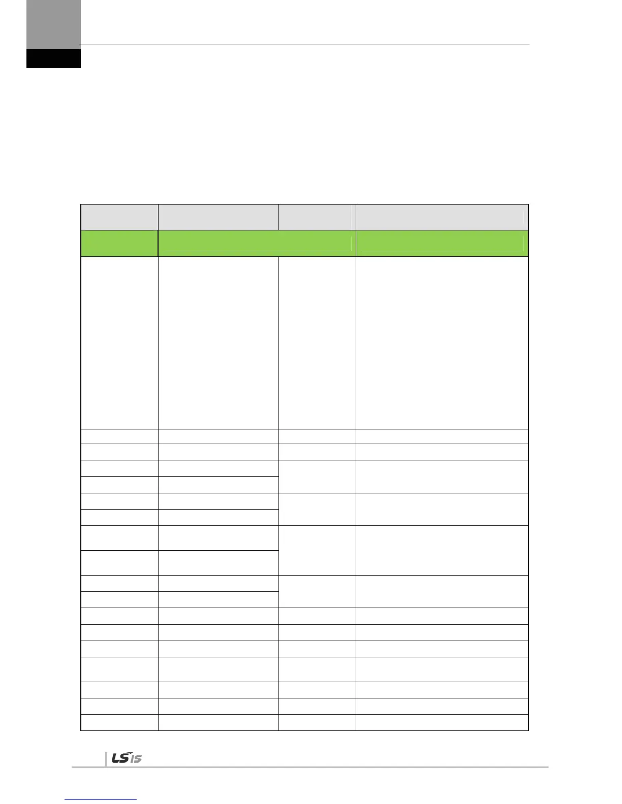
6.3.1 Operation Status Parameter Communication
Address Table
Communicatio
n Address
Parameter Name
Parameter
Number
Material Type
(Decimal
Number)
Operation Status Display Parameter
0 Current operation status St - 00
INT16
BIT0: Alarm
BIT1: Servo on
BIT2: Warning
BIT3: CCW limit
BIT4: CW limit
BIT5: Zero speed
BIT6: In speed
BIT7: In position
BIT8: Power ready
BIT9: Analog command active
BIT10 - BIT13: Control mode
(0: Trq, 1: Spd, 2: Pos, 3: Spd/Pos,
4: Trq/Spd, 5: Trq/Pos)
2 Current operation speed St - 01 INT16
4 Current command speed St - 02 INT16
6 Tracking position pulse - L
St - 03 INT32
8 Tracking position pulse - H
10 Position command pulse - L
St - 04 INT32
12 Position command pulse - H
14
Remaining position pulse -
L
St - 05 INT32
16
Remaining position pulse -
H
18 Input pulse frequency – L
St - 06 INT32
20 Input pulse frequency - H
22 Current operation torque St - 07 INT16
24 Current command torque St - 08 INT16
26 Accumulated overload rate St - 09 INT16
28
Instantaneous maximum
load factor
St - 10 INT16
30 Torque limit value St - 11 INT16
32 DC Link Voltage St - 12 UINT16
34 Regenerative overload St - 13 UINT16

 Loading...
