4. Parameters
4-20
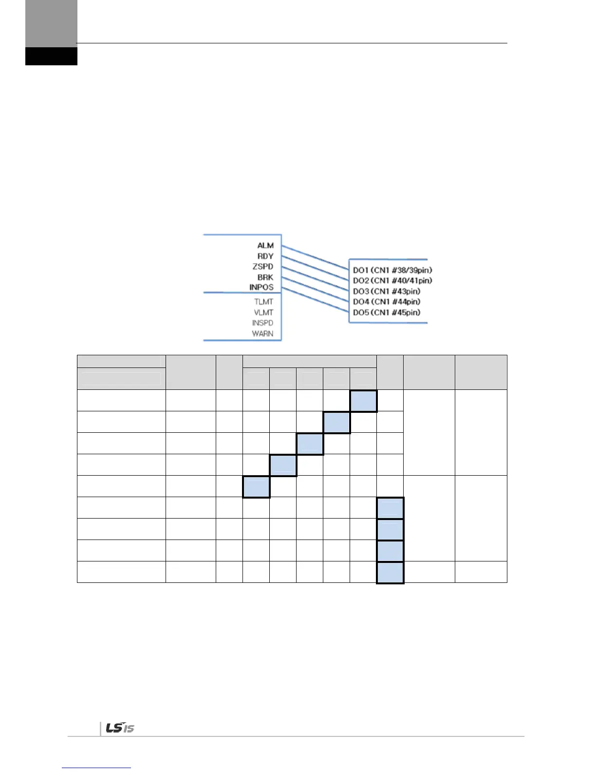
4.1.8 External Output Signal and Logic Definition
The following explains output signal allocation and the method of checking allocation status.
(1) Output Signal Allocation
Output signal definition: [P2-05], [P2-06], [P2-07]
Output signal logic definition: [P2-10]
The default output signal allocation is as follows:
Signal Name
Output
Signal
Alwa
ys
Alloc
ated
CN1 Pin Default Allocation Number
Not
Alloc
ated
Internal
Parameter
Default
Value
Parameter Allocation 45 44 43 40/41 38/39
Alarm
[P2-05].Set Digit 1
ALARM F 5 4 3 2
1 0
[P2-05] 0x4321
Servo Ready
[P2-05]. Set Digit 2
READY F 5 4 3
2 1 0
Zero speed achieved
[P2-05]. Set Digit 3
ZSPD F 5 4
3 2 1 0
Brake
[P2-05]. Set Digit 4
BRAKE F 5
4 3 2 1 0
Position reached
[P2-06]. Set Digit 1
INPOS F
5 4 3 2 1 0
[P2-06] 0x0005
Torque limit reached
[P2-06]. Set Digit 2
TLMT F 5 4 3 2 1
0
Speed limit reached
[P2-06]. Set Digit 3
VLMT F 5 4 3 2 1
0
Speed achieved
[P2-06]. Set Digit 4
INSPD F 5 4 3 2 1
0
Warning
[P2-07]. Set Digit 1
WARN F 5 4 3 2 1
0 [P2-07] 0x0000
NOTE 1) CN1 connector pin is not allocated when the default value is "0".
Output Signal
Output Allocation Number

 Loading...
