3. Wiring Method
3-21
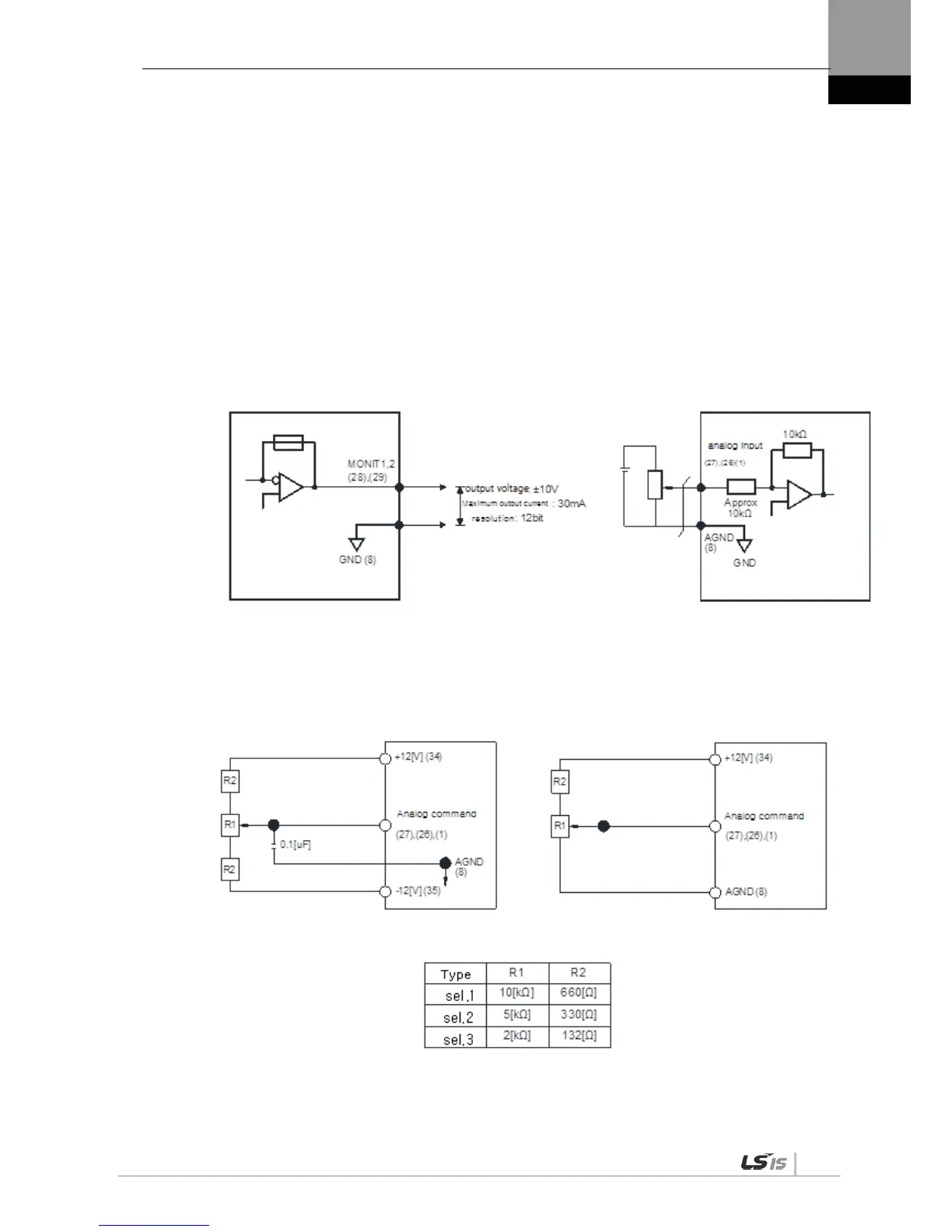
3.5.3 Analog Input/Output Signals
1. Keep GND as 0 [V] of control power.
2. Keep the input signal command voltage within ±10 [V], and input impedance at 22 [㏀].
3. Output signal voltage for Monitor 1 (No. 28) and Monitor 2 (No. 29) is ±10 [V].
Configure wiring as shown in the following image when you adjust analog input with
parameter resistance by using power supplied by the drive.
Do not exceed the maximum output capacity of 30 [㎃].
<Servo Drive >
<Analog Input Example>
<Analog output>
<Analog input>

 Loading...
