1. Product Components and Signals
2-13
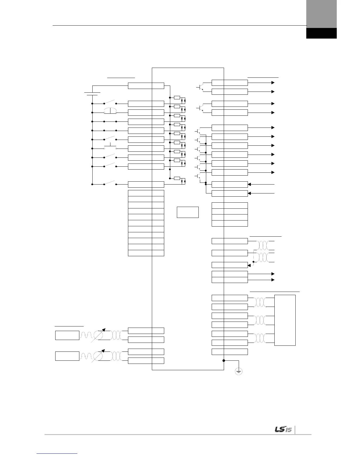
1.2.5 Example of Torque Operation Mode Wiring
EMG 18
CWLIM 19
CCWL IM 20
DIR 46
ALMRST 17
SVON 47
ALARM+38
ALARM-39
READY+40
READY-41
ZSPD43
BR AKE44
50+24V IN
GND2424
ALO016
ALO115
ALO214
GND2425
DC 24V
CN1
(
DI 9
)
(
DI8
)
(
DI7
)
(
DI6
)
(
DI5
)
(
DI4
)
(
DI3
)
(
DI2
)
(
DI1
)
(
DO1
)
(
DO2
)
(
DO3
)
(
DO4
)
(
DO5
)
VLMT**
TLMT**
WARN**
28
29
37
AO32
/AO33
BO30
/BO31
ZO4
/ZO5
SG36
-10V~ +10V
-10V~ +10V
34
35
3.3kΩ
**
**
**
**
**
**
**
ZCLAMP **
**
ABS_R
ST
SPD3 21
SPD2 2 2
SPD1 23
STOP 48
TLMT
_
ABS_RQ
EGEAR1
EGEAR2
PCON
GAIN2
PCLR
_
MODE
**
SPDCOM 27
GND 8
TRQCOM 1
GND 8
-10V~ +10V
-10V~ +10V
MONIT1
MONI T2
GND
+12VA
-12 VA
45
INPOS
INSPD**
Digital Input
Digital Output
Analog Output
Encoder Pulse Output
Connect to Connector Case
Analog Torque
Command/Limit
Upper Level
Controller
Note 2)
Note 2)
Note 1)
Note 1)
Analog Speed
Command/Limit
Analog Input
Note 1) Input signals DI1 to DIA and output signals DO1 to DO5 are default signals allocated by the factory.
Note 2) **These are non-allocated signals. You can change their allocation by setting parameters. For
information, refer to "4.1.6 External Input Signal and Logic Definition" and "4.1.8 External Output Signal and
Logic Definition."

 Loading...
