3. Wiring Method
3-4
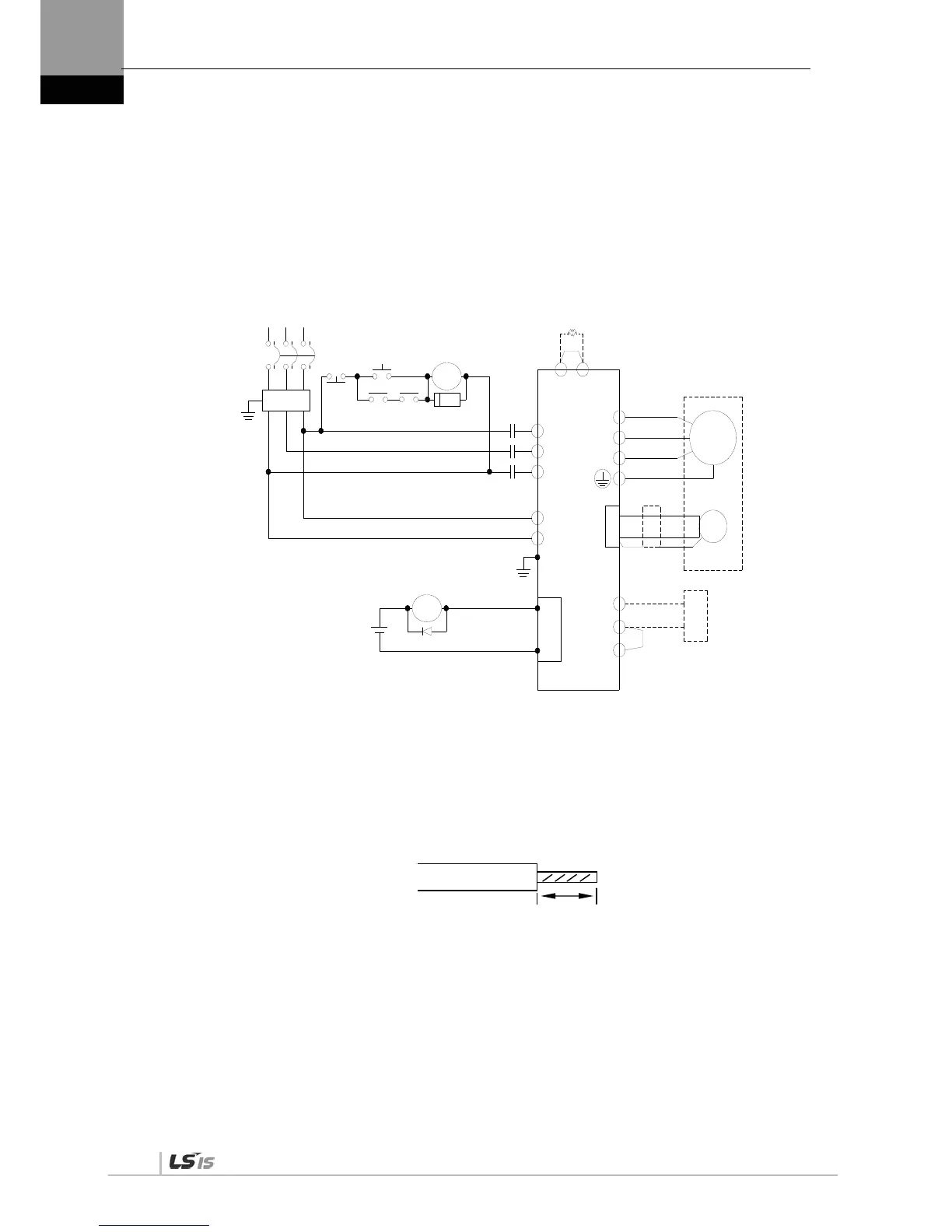
3.2 Power Wiring
3.2.1 XDL-L7 Drive Wiring Diagram [XDL-L7SA001□ -
XDL-L7SA035□]
U
V
W
L1
L2
L3
C1
C2
B+
B
BI
38
39
CN1
RA
M
E
Alarm-
Alarm+
1Ry
RA
1SK
1Ry1MC
+24V
NF
1MC
RST
서보드라이브
(200~230V)
Main
OFF
Main
ON
인코더
외부
회생저항
주1)
주2)
PO
PI
DC 리액터
NOTE 1) It takes approximately one to two seconds until alarm signal is output after you turn on the main
power. Accordingly, push and hold the main power ON switch for at least two seconds.
Short-circuit B and BI terminals before use. Regenerative resistance of XDL-L7SA001-XDL-L7SA004 (50
[W], 100 []), XDL-L7SA010 (100 [W], 40 []), and XDL-L7SA035 (150 [W], 13 []) exist inside.
If regenerative capacity is high because of frequent acceleration and deceleration, open the short-
circuit pins (B, BI) and connect external regenerative resistance to B and B+.
Remove approximately 7-10 [mm] of the sheath from the cables for the main circuit power and attach crimp
terminals. (Refer to “3.2.2 Power Circuit Electric Sub Assembly Standards.”)
Connect or remove the main circuit power unit wiring after pushing the button of the XDL-L7SA001 – XDL-
L7SA010 drive terminal. For XDL-L7SA035 drive, use a (-) slot screwdriver for connection and
removal.
Servo Drive
Note 1)
DC Reactor
Encoder
Note 2) External
Regenerative Resistance
7~10 ㎜

 Loading...
