Home
LSIS
Controller
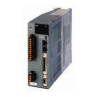
XDL-L7SA002X
LSIS XDL-L7SA002X User Manual
4
of 1
of 1 rating
275 pages
Give review
Manual
Specs
To Next Page
To Next Page
To Previous Page
To Previous Page
Loading...
5. Handling and O
peration
5-2
5.1.5
System P
ara
meter Check
1.
Is the motor ID setting [P0-00] in good condition?
2.
Are the encoder type [P0-01] and the encod
er pulse [P0-02] in good condition
?
3.
Is control gain set to an appropriate value?
*Note: Refer to "Appendix 2
T
est Drive Procedure."
143
145
Table of Contents
Default Chapter
9
Table of Contents
9
Product Components and Signals
13
Part Names
15
System Configuration
20
Wiring Diagram of the Entire CN1 Connector
22
Example of Position Operation Mode Wiring
23
Example of Speed Operation Mode Wiring
24
Example of Torque Operation Mode Wiring
25
Examples of Speed / Position Operation Mode Wiring
26
Signal
29
Analog Input Contact Signal
30
Monitor Output Signal and Output Power
31
Encoder Output Signal
32
2 Installation
33
Load Device Connection
34
Servo Drive
35
Installation Inside the Control Panel
36
Power Wiring
37
3 Wiring Method
39
XDL-L7 Drive Block Diagram [XDL-L7SA008□ - XDL-L7SA035□]
40
XDL-L7 Drive Block Diagram [XDL-L7SA050□ ]
41
Power Wiring
42
XDL-L7 Drive Wiring Diagram [XDL-L7SA050□]
43
Dimensions for Power Circuit Electrical Parts
44
Example of Connecting to PLC
48
Timing Diagram
55
Timing Diagram at the Time of Alarm Trigger
56
Control Signal Wiring
57
Contact Output Signal
58
Analog Input/Output Signals
59
Pulse Train Input Signal
60
Encoder Output Signal
61
Quadrature Encoder Signaling Unit (CN2) Wiring
62
Serial Encoder Signaling Unit (CN2) Wiring
63
Multi Turn Encoder Signal Unit(CN2) Wiring
65
Transmission of Absolute Encoder Data
67
4 Parameters
69
Status Summary Display
70
Parameter Handling
72
Data Display
76
External Input Contact Signal Display [St-14]
78
External Input Signal and Logic Definition
79
External Output Contact Signal Display [St-15]
87
External Output Signal and Logic Definition
88
Parameter Description
94
Operation Status Display Parameter
95
System Setting Parameter
98
Control Setting Parameter
102
Input/Output Setting Parameter
106
Speed Operation Setting Parameter
109
Position Operation Setting Parameter
111
Operation Handling Parameter
114
Operation Status Display
118
I/O Status Display
119
Version Display
120
Parameter Setting
121
Control Parameter Setting
124
Analog Input/Output Parameter Setting
129
Input/Output Contact Point Parameter Setting
130
Speed Operation Parameter Setting
133
Position Operation Parameter Setting
134
Alarms and Warnings
136
Servo Warning Status Summary Display List
138
Motor Type and ID (to be Continued on the Next Page)
139
5 Handling and Operation
143
System Parameter Check
144
Handling
145
Program JOG Operation [Cn-01]
147
Alarm Reset [Cn-02]
148
Reading Alarm History [Cn-03]
149
Alarm History Reset [Cn-04]
150
Auto Gain Tuning [Cn-05]
151
Phase Z Search Operation [Cn-06]
152
Input Contact Forced ON/OFF [Cn-07]
153
Output Contact Forced ON/OFF [Cn-08]
155
Parameter Reset [Cn-09]
157
Automatic Speed Command Offset Correction [Cn-10]
158
Automatic Torque Command Offset Correction [Cn-11]
159
Manual Speed Command Offset Correction [Cn-12]
160
Manual Torque Command Offset Correction [Cn-13]
161
Absolute Encoder Reset [Cn-14]
162
Instantaneous Maximum Load Factor Initialization [Cn-15]
163
Parameter Lock [Cn-16]
164
Current Offset[Cn-17]
165
6 Communication Protocol
167
Communication Specifications and Cable Access Rate
168
Communication Protocol Base Structure
169
Protocol Command Codes
171
XDL-L7 Servo Drive Communication Address Table
176
System Parameter Communication Address Table
178
Control Parameter Communication Address Table
180
Input/Output Parameter Communication Address Table
182
Speed Operation Parameter Communication Address Table
183
Position Operation Parameter Communication Address Table
184
7 Product Specifications
185
Product Features
186
Outline Drawing
217
Servo Drive
234
Outline Drawing
236
Options and Peripheral Devices
238
Precautions
251
Parts Replacement Cycle
252
8 Maintenance and Inspection
251
Servo Motor
253
Servo Drive
254
9 Appendix
267
Test Drive Procedure
270
User Manual Revision History
274
4
Based on 1 rating
Ask a question
Give review
Questions and Answers:
Need help?
Do you have a question about the LSIS XDL-L7SA002X and is the answer not in the manual?
Ask a question
LSIS XDL-L7SA002X Specifications
General
Brand
LSIS
Model
XDL-L7SA002X
Category
Controller
Language
English
Related product manuals
LSIS XGL-EFMTB
212 pages
LSIS XBF-DC04A
618 pages
LSIS XEC-DP64H
315 pages
LSIS XBF-AH04A
618 pages
LSIS XEC-DN60SU
315 pages
LSIS XBC-DR40SU
384 pages
LSIS XP10BKA/DC
226 pages
LSIS XBC-DN20SU
384 pages
LSIS XBC-DN60SU
384 pages
LSIS XBC-DN30SU
384 pages
LSIS XBC-DN64H/DC
315 pages
LSIS XBC-DN32H/DC
315 pages