1. Product Components and Signals
2-18
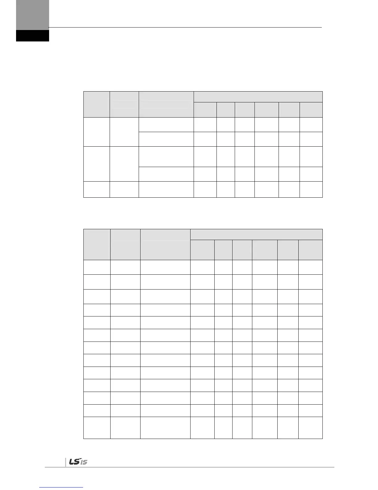
1.3.2 Analog Input Contact Signal
Pin
Number
Name Description
Applicable Modes
Position Speed Torque
Speed
/Position
Speed
/Torque
Position
/Torque
27 SPDCOM
Analog speed
command (-10-+10 [V])
X O X O/X O/X X
Analog Speed Limit
(-10-+10 [V])
X X O X X/O X/O
1 TRQCOM
Analog Torque
Command
(-10-+10 [V])
X X O X X/O X/O
Analog torque limit
(-10-+10 [V])
O O X O O/X O/X
8
37
GND
Grounding for analog
signals
O O O O O O
1.3.3 Digital Output Contact Signal
Pin
Number
of
Factory
Setting
Name Description
Applicable Modes
Position Speed Torque
Speed
/Position
Speed
/Torque
Position
/Torque
16 ALO0
Alarm group contact
output 1
O O O O O O
15 ALO1
Alarm group contact
output 2
O O O O O O
14 ALO2
Alarm group contact
output 3
O O O O O O
38 / 39 ALARM +/- Alarm O O O O O O
40 / 41 READY +/- Ready for operation O O O O O O
43 ZSPD Zero speed reached O O O O O O
44 BRAKE Brake O O O O O O
45 INPOS Position reached O X X X/O X O/X
Allocate TLMT Torque limit O O O O O O
Allocate VLMT Speed limit O O O O O O
Allocate INSPD Speed reached X O X O/X O/X X
Allocate WARN Warning O O O O O O
24
25
GND24
Input/output contact
Grounding of drive
power (24 [V])
O O O O O O

 Loading...
