4. Parameters
4-57
(1) Inertia Ratio Setting [P1-00]
An inertia ratio shall be set by calculating load inertia from the machine system and rotor
inertia from the motor specification table.
Setting inertia ratio against load is an important control parameter for the operation of the
servo. Setting accurate inertia ratio is crucial for optimal servo operation.
The following table contains control gain recommendations for different categories of inertia
ratio:
Motor
Flange
Inertia Ratio Gain Range
Category
[Inertia]
(Multiple)
Position
Proportional
Gain
Speed
Proportional
Gain
Speed Integral
Gain
40
~ 80
Low inertia 1 ~ 5 40 ~ 90 400 ~ 1000 10 ~ 40
Medium
inertia
5 ~ 20 20 ~ 70 200 ~ 500 20 ~ 60
High inertia 20 ~ 50 10 ~ 40 100 ~ 300 50 ~ 100
* Inertia ratio can be tuned during a test drive if it is hard to calculate.
(2) Position Control Gain
Position command: Count the position command pulses entering from outside, and converts them
into position commands, apply an electric gear ratio, and then pass through [P1-03] position
command filter, and use it as an internal position command. In the case that Numerator of electric
gear is bigger, a change of external input position command pulse influences on a change of
internal position command. And this influence is getting bigger. So there is need to adjust ‘[P1-03]
position command filter time constant’
Current position: Count pulse signals received from the encoder and convert them to current
position by using electronic gear ratio settings.
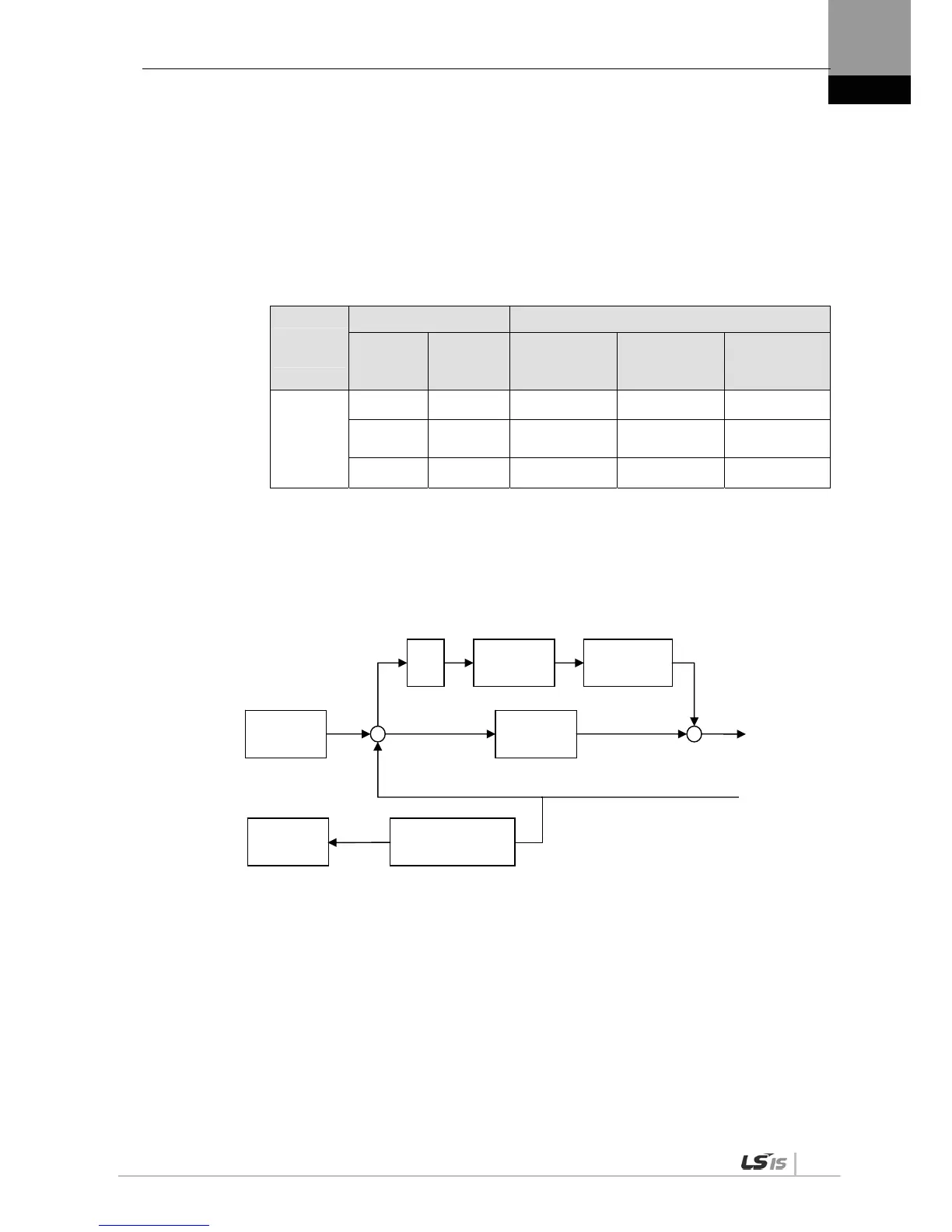
Position proportional gain [P1-01] and [P1-02]: Convert the difference between the position
command and the current position into a speed command by multiplying it by position proportional
gain.
* Recommended value = speed proportional gain [P1-06] / 10
Differ
entiati
on
FF filter time
constant
Feedforward gain
[P1-04]
Current position
Proportional
gain
Position error
+
-
+
+
Speed
Command
Position
command
Pulse output
Prescale
[P0-14]

 Loading...
