6. Communication Protocol
6-4
(3) Protocol Packet Code
Node ID
Indicates the exchange number of the servo drive to send.
Set the exchange number of the servo drive to [P0-05].
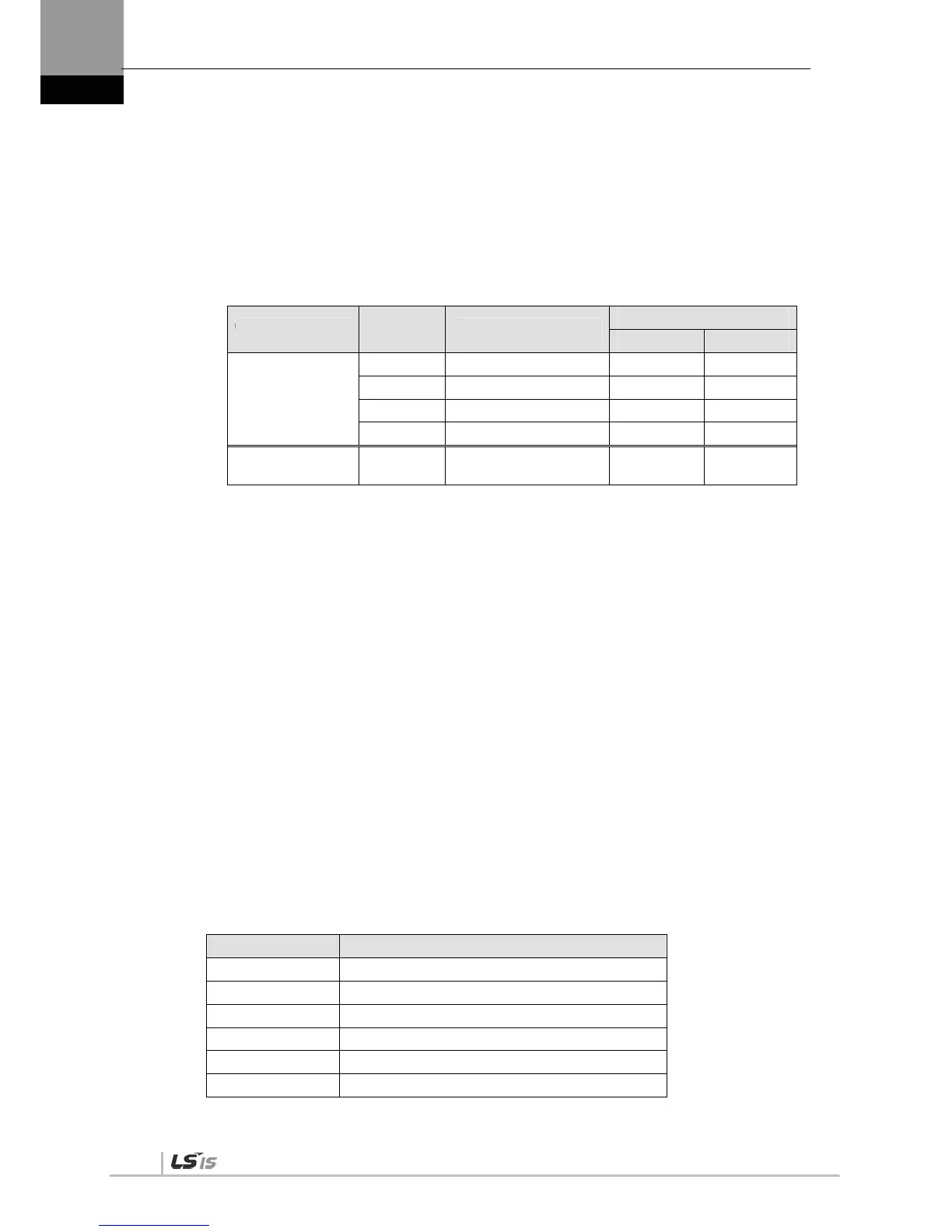
Function Code
The following are the Modbus-RTU standard function codes supported by the XDL-L7 servo drive.
D
a
t
a
[
S
e
n
d
i
n
g]
For read register commands, the Modbus address, the number of registers, and the number of
bytes will be set. For write register commands, the Modbus address, the number of bytes, and
other necessary values will be set.
[Receiving]
In the case of read register commands, normal responses are received with the same node ID
and function code as they are sent. In terms of data, registers are received according to the
order of sent registers.
In the case of write single register commands, the same data as those sent are received. In the
case of write multi registers, the start address of the register, whose data were to be used with
the write multi register command, and the number of registers are received.
Abnormal responses consist of node ID, error code, and exception code. The packet structure is
the same for all abnormal responses regardless of their function codes.
(4) CRC
Enter the 16-bit CRC check sum. Send 1 byte of MSB and LSB each.
(5) Exception Code
The followings are the exception codes for all abnormal responses of all function codes
supported in the XDL-L7 servo drive.
Exception Code Description
0x01 Unsupported function codes
0x02 Invalid register address
0x03 Non-matching node IDs or CRC check errors
0x04 Command handling failure
0x05 Waiting(state of preparing data)
0x06 Locking(state of locking parameter)
Category
Comman
d Code
Details
Purpose
Read Write
Public function
code
0x03 Read single register
0x03 Read multi register
0x06 Write single register
0x10 Write multi register
User defined
function code
0x6A Read each block register

 Loading...
