4. Parameters
4-13
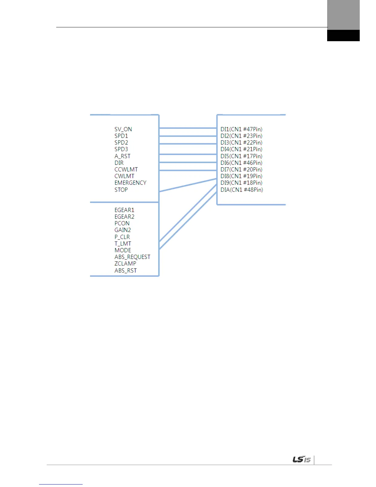
(2) Example of Changing Input Signal Allocation
The input signal definition can be changed in [P2-00], [P2-01], [P2-02], [P2-03], and [P2-04].
The input signal logic definition can be changed in [P2-08] and [P2-09].
Allocate input signals as shown in the following table:
Input Signal
Input Allocation Number

 Loading...
