Section 4 – FLY-JIB INSTALLATION AND STOWAGE Mini-Crawler Crane M A E D A
4-158 1/2019 MC405C-3
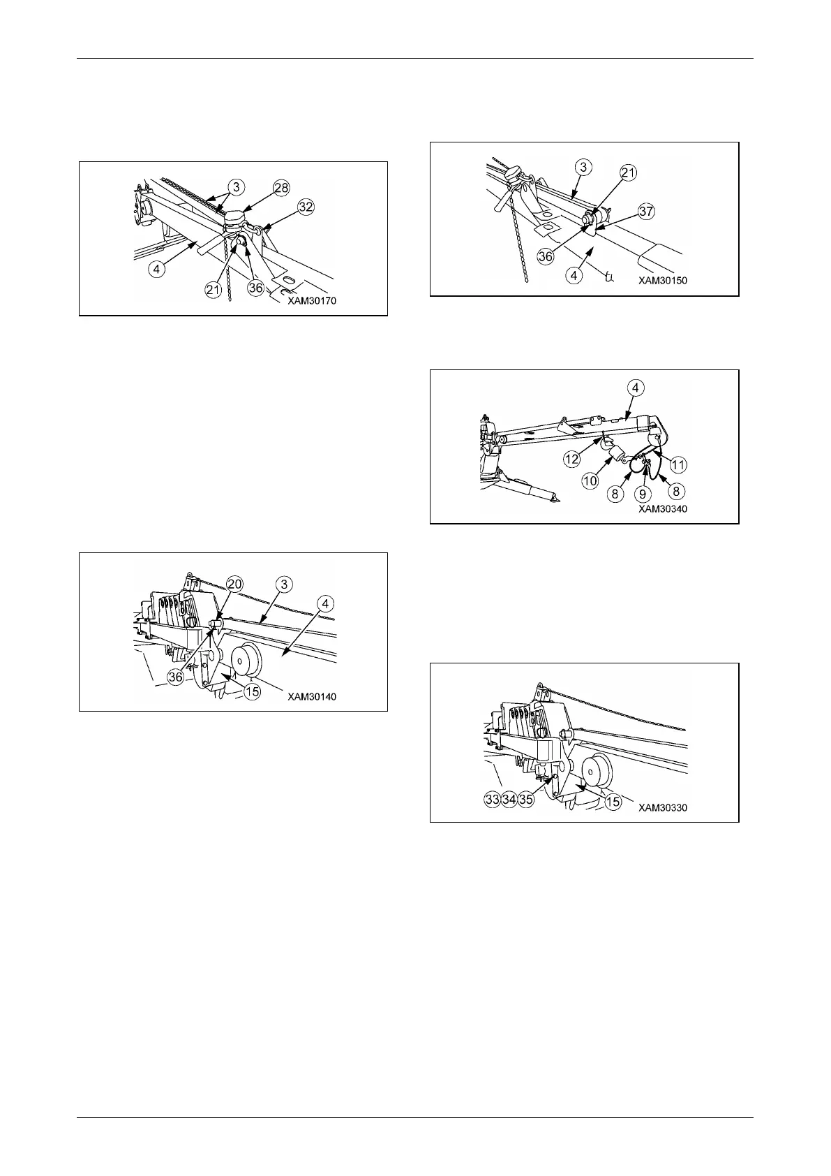
12. Pull lynch-pin (36) out from position pin (21)
inserted at the bracket (32) of No.1 Fly-jib
bracket, then pull position pin (21) (length:
135mm) out from the bracket (32.).
Fig. 4-466
NOTICE:
• Hold two supporting rods (3) whilst pulling
position pin (21) out. If you were not hold
supporting rod (3), they will drop.
• Position pin (21) pulled out will be used to
connect supporting rod (3) with No.1 Fly-jib
bracket later.
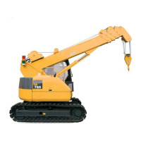
13. Insert two supporting rods (3) into upside of
No.1 Fly-jib bracket (15), and put positions of
the hole together.
Fig. 4-467
14. Insert position pin (20) (length: 135mm) into
the hole on the upside of No.1 Fly-jib bracket
(15), and lock position pin (20) firmly by
lynch-pin (36).
NOTICE: Supporting rod (3) is composed of two
rods. Move the rod one by one when you change
the position of supporting rod (3).
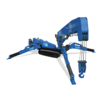
15. Operate lever block (28) to move No.1 Fly-jib
(4), and put the hole of supporting rod (3)
and No.1 Fly-jib (4) bracket (37) together.
16. Insert position pin (21) (length: 135mm) into
the hole of No.1 Fly-jib (4) bracket (37), then
fix position pin (21) firmly by lynch-pin (36).
Fig. 4-468
17. Hang single fall hook (10) on the hook holder
(12) underneath the No.1 Fly-jib (4).
Fig. 4-469
NOTICE: Slacken off wire rope (11) slightly.
18. Remove four attachment bolts (33)
(M12x30L), four washers (34), and four nuts
(35) which are used on the No.1 Fly-jib
bracket (15).
Fig. 4-470
19. Remove lever block (28).