Section 4 – FLY-JIB INSTALLATION AND STOWAGE Mini-Crawler Crane M A E D A
4-164 1/2019 MC405C-3
CAUTION:
• If you attach bar guide A (23) to machine,
replace washers (64) to each part with the
same number of washers as recorded when
you removed it.
• Washer on the each bar guide and
attachment bolt.
• Washer on the each bar guide and between
main booms.
• When you attach new Fly-jib, use number of
washers (64) as directed below, and set Bar
guide A (23) of Stowage Bar so that it faces
slightly upper side.
• Use washer one by one to each attachment
bolt on bar guide.
• Use washer one by one to bar guide A (23)
and between main booms.
• Do not use washer for bar guide B (24) and
between main boom.
• When you attach bar guide A (23), tighten
attachment bolt lightly. It is necessary to
remove attachment bolt (63) again because
of regulating storage bar height.
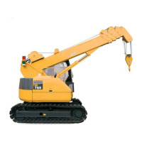
3. Push storage bar (16) into bar guide A (23)
and bar guide B (24).
WARNING! Hold storage bar (16) firmly, until
bar guide C (25) is attached.
4. Set bar guide C (25) into bar guide A (23),
and tighten it by four attachment bolts (61)
and plural washers (62).
5. Set bar guide D (26) into bar guide B (24),
and tighten it by four attachment bolts (61)
and plural washers (62).
Fig. 4-493
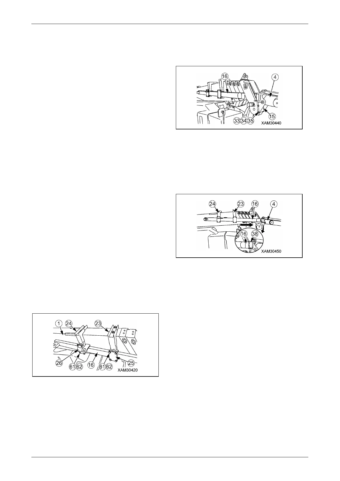
6. Hang wire rope to No.1 Fly-jib (4), then
operate crane to set No.1 Fly-jib (4) to Fly-jib
bracket (15) on the head of main boom.
7. Use four attachment bolt (33) (M12x30L),
four washers (34) and four nuts (35) to
tighten attach Fly-jib bracket (15) with main
boom.
Fig. 4-494
NOTICE: Insert attachment bolt from main boom
side.
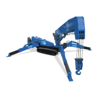
8. Move storage bar (16) to No.1 Fly-jib (4)
side, and confirm whether storage bar (16)
could be inserted smoothly into N0.1 Fly-jib
bracket (38).
Fig. 4-495
CAUTION: In case the storage bar (16) were
not to insert smoothly into No.1 Fly-jib
bracket (38), confirm condition. After
confirmation, if there is something wrong
with storage bar, reset bar in accordance with
"METHOD to REGULATE THE HEIGHT of
STORAGE BAR" to re-set it.
1. In case storage bar (16) faced to upper
side toward bracket (38), it indicate bar
guide A (23) is on a higher position than
bar guide B (24).