11 Hardware
3. Connect a power cable to each external power supply.
4. Attach one end of the DIN cable (provided in the module accessories kit) to the connector
labeled Module Connection on the back of the new unit.
5. Attach the other end of the DIN cable to the separate power adapter.
6. Attach the hardwired power adapter cable to the lower connector labeled Module Connection
on the back of the analysis module.
7. Plug the external power supply cables into electrical wall outlets.
8. Power ONthe control module. If running the application software, start the application.
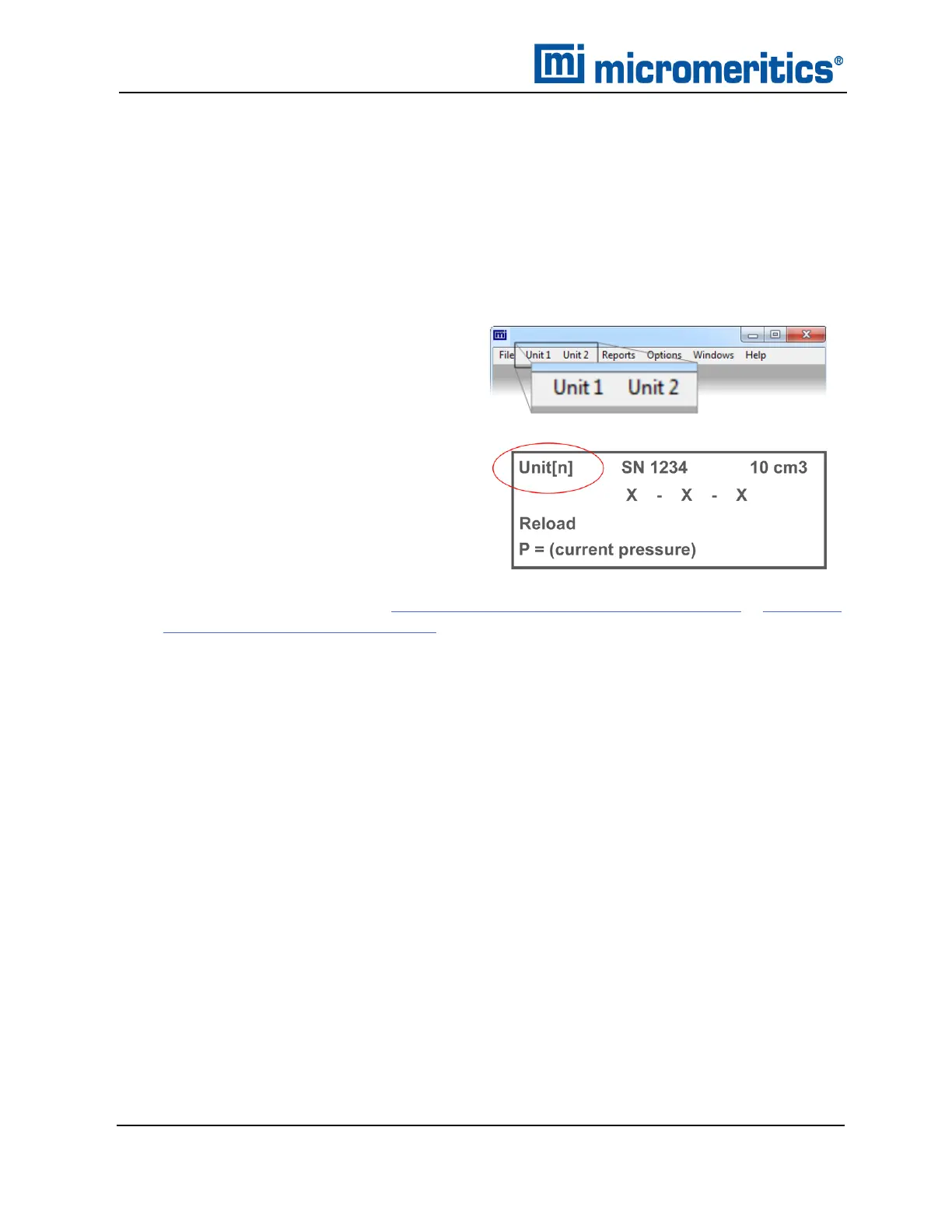
9. Verify the unit is recognized:
n If running the application software,
Unit [n] menus are added to the menu
bar for each analysis module con-
nected.
n If using the keypad for analysis, press
Alt + CHOICE + 2 to access the addi-
tional analysis module. Unit [n]
appears in the upper left corner of the
display.
10. Calibrate the pycnometer. See Calibrate Using the Keypad on page10 - 14 or Calibrate
Using the Software on page10 - 1.
11 - 2
AccuPyc II 1345 Operator Manual
134-42851-01 (Rev A) — Jan 2021
 Loading...


