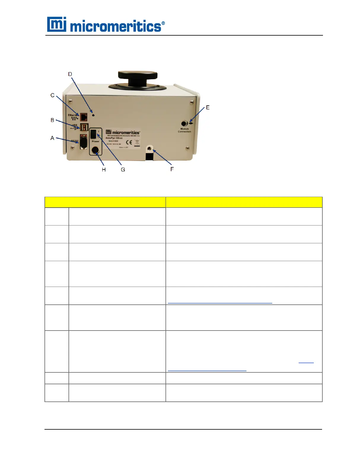
BACK COMPONENTS
Component
Description
Dust filter (not shown) (For 2000 cm
3
units and high pressure units only.)
Traps sample dust to protect internal valves.
A
RS232 port Used to transmit data only when using the keypad func-
tion. Also used to connect to the analytical balance.
B
USB connectors Use for connecting a keyboard, printer, or balance to
the instrument.
C
Ethernet port Provides for setting up for e-mailing reports, sending
data to a web browser, or interfacing with the AccuPyc
Windows application.
D
Brightness control Used to adjust the brightness of the display. See
Brightness Control on page11 - 4.
E
Analysis module connector Used to connect up to five analysis modules to the ini-
tial control / analysis module. Each module contains
analysis module input and output connectors.
F
Gas inlet port Use to connect the analysis gas; helium is recom-
mended. If multiple analysis modules are attached,
each module contains a gas inlet port. Multiple gases
can be attached using the Multigas option. See Multi-
gas Option on page16 - 1.
G
ON/OFF switch For powering the analyzer on and off.
H
Power connector For connecting the power source to the instrument
using a mini-DIN cable.
Back Components
Instrument Components
AccuPyc II 1345 Operator Manual
134-42851-01 (Rev A) — Jan 2021
1 - 3
 Loading...


