1 About the AccuPyc II
INSTRUMENT COMPONENTS
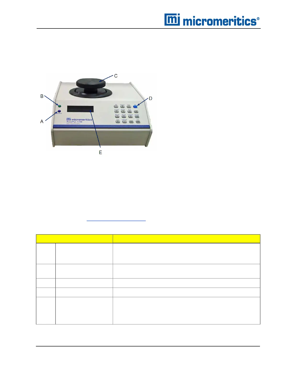
FRONT COMPONENTS
The sample chamber, located on the top panel, is where the sample cup is placed for analysis.
The sample chamber should remain capped except when inserting or removing a sample. When left
uncapped, water vapor adsorbs on the inner surface of the chamber or the chamber temperature
becomes unstable; either condition can affect analysis results. If water vapor accumulates in the
chamber, the pycnometer must be purged.
The standalone control module, often used for the Glove Box pycnometer, does not contain a
sample chamber. See Glove Box on page1 - 9.
Component
Description
A
Active indicator A blue LED which illuminates when an operation is in progress.
It is included on all analysis modules. It is not included on stan-
dalone control modules.
B
Power indicator A green LED which illuminates when the analyzer is powered
on.
C
Sample chamber For inserting sample material.
D
Keypad For operating the pycnometer without the Windows application.
E
Display window Displays Remote Operation when the Windows application is
being used.
The AccuPyc can be operated in the keypad mode when the
Windows application is closed.
Front Components
1 - 2
AccuPyc II 1345 Operator Manual
134-42851-01 (Rev A) — Jan 2021
 Loading...


