SHOW INSTRUMENT SCHEMATIC
Unit [n] >Show Instrument Schematic
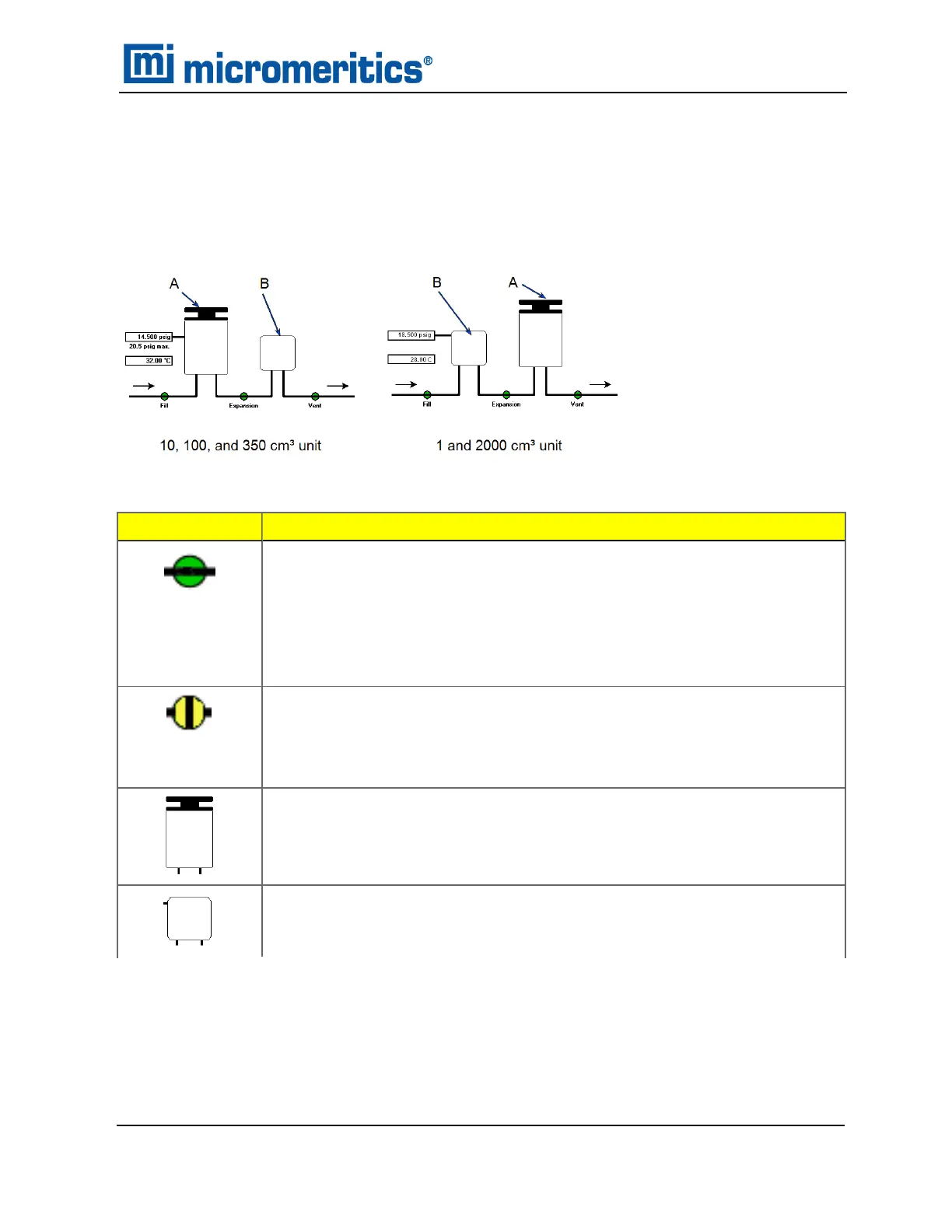
Use to display an analyzer schematic. To operate the valves and elevator from this window, manual
control must be enabled (Unit [n] > Enable Manual Control).
A. Sample chamber
B. Expansion chamber
Icon or Symbol
Description
Open Valve. Green indicates an open valve.
n Fill Valve. Allows gas to pressurize the first chamber.
n Expansion Valve. Allows gas from the first chamber to flow into the second
chamber.
n Vent Valve. Vents gas from the system.
Closed Valve.
n Yellow — indicates a closed valve with manual control enabled.
n White — indicates a closed valve with manual control not enabled.
Sample Chamber.
Expansion Chamber.
Analyzer Schematic Icons
Show Instrument Schematic
AccuPyc II 1345 Operator Manual
134-42851-01 (Rev A) — Jan 2021
3 - 11
 Loading...


