098-00720-000 Revision D1 – February, 2018 SyncServer 600 Series User’s Guide 35
Chapter 1 Overview
Physical Description
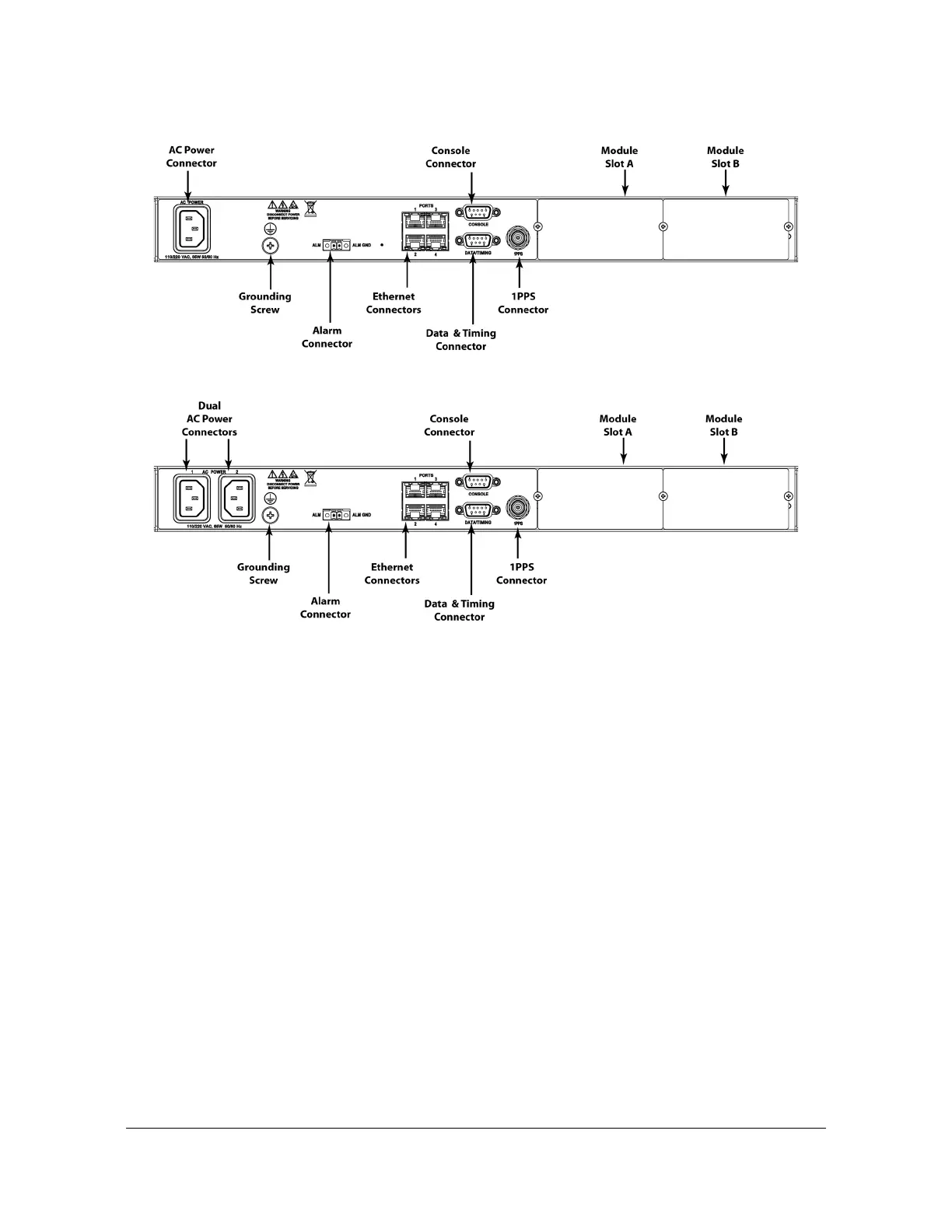
Figure 1-16. SyncServer S650i Rear Panel - Single AC Version
Figure 1-17. SyncServer S650i Rear Panel - Dual AC Version
Communications Connections
The SyncServer S6x0 is primarily controlled through the web interface available on
LAN 1. Limited functionality is available via the console serial port.
Ethernet Management Port - LAN1
Ethernet port 1 is the management port that is used to access the web interface.
This port is located on the rear panel of the SyncServer S6x0 and is a standard
100/1000 Base-T shielded RJ-45 receptacle. To connect the SyncServer S6x0 to an
Ethernet network, use a standard twisted-pair Ethernet RJ-45 cable (CAT5
minimum). Configurable to 100_Full or 1000_Full or Auto :100_Full / 1000_Full.
Serial Console Port
The serial port connection is made through a DB-9 female connector on the rear
panel of the SyncServer S6x0. This port, which supports a baud rate of 115.2k
(115200-8-N-1), allows you to connect to a terminal or computer using a terminal
emulation software package. When connecting to this port, use a shielded serial
direct connect cable.
This port is also used for serial data (NENA ASCII time code, Response mode).
Figure 1-18 shows the DB-9 female connector for the serial port.